2
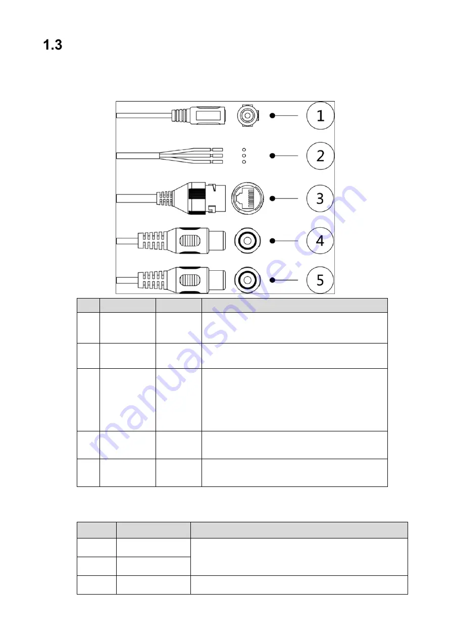
Cables and Connectors
Cable type might vary with device.
Waterproof all cable joints with insulating and waterproof tape to avoid short circuit and
water damage.
Ref. Port Name
Connector Description
1
Power
Power port. Input 12 VDC power supply.
Use in accordance with device label instructions.
2
Alarm I/O
Input/output for alarm signals.
3
Network Port RJ-45
Connect to standard Ethernet cable.
Note: Certain devices support Power over Ethernet.
Check the specific device to determine if the device
accepts PoE and use an appropriate Ethernet cable
and network to supply power.
4
Audio Input
RCA
Input audio port from an external audio pick-up (not
available on all dome cameras).
5
Audio Output RCA
Output audio port to an external speaker (not
available on all dome cameras).
1.3.1 Alarm Connections
Ref.
Connector Name Description
1
ALARM_OUT1
Alarm output port 1 outputs alarm signal to alarm device.
When connecting to alarm device, only the ALARM_OUT 1
port and ALARM_OUT_GND 1 port with the same number
can be used together.
2
ALM_OUT_GND1
5
ALM_IN_GND
Alarm input GND.
Summary of Contents for N53AF5Z
Page 24: ...13...


