6
3 Installation and Configuration
3.1 Camera and Cables
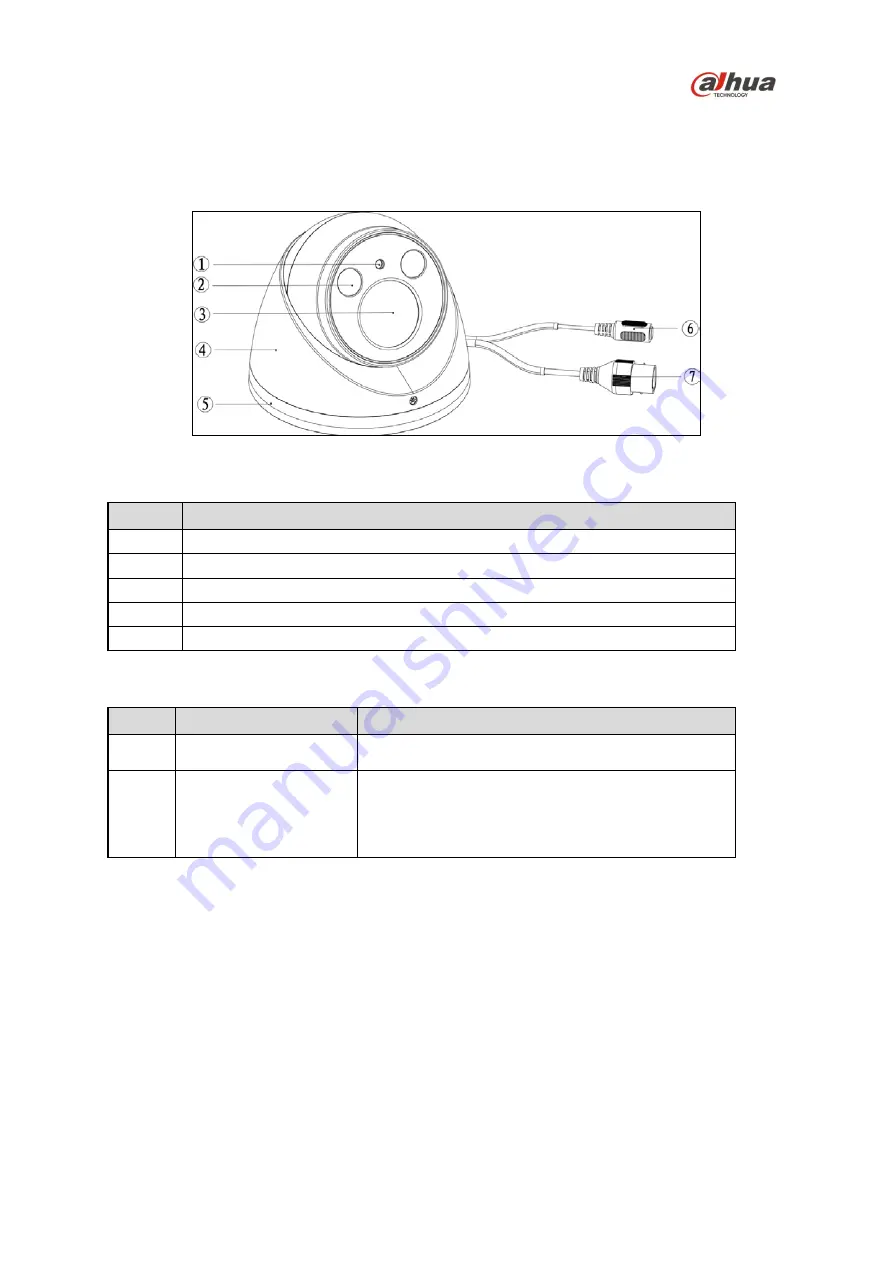
Figure 3-1
Camera Components
Ref
Description
1
Photosensor
2
IR Light
3
Lens
4
Dome Enclosure
5
Dome Pedestal
Cable Connections
Ref
Port Name
Function
6
Power Input Port
Power port. Input 12 VDC
Use power according to the device tag.
7
LAN
Connect to standard Ethernet cable.
Note:
Certain devices support Power over Ethernet.
Check the specific device to determine if the device
accepts PoE and use an appropriate Ethernet cable
and network to supply power.


