background image

Web

  Operations

    141


To delete an added device, select it, and then click 

Delete

; to modify the 

information of an added device, click 

  or double-click the device. 

5.3.4 Configuring Record Settings 

The record mode is consisted of manual mode and auto mode. You can also enable or disable 

the snapshot function. 


Auto: The recording starts automatically according to the record type and recording time as 

configured in the recording schedule. 


Manual: Keep general recording for 24 hours for the selected channel. 

CAUTION


Manual recording operation requires the user have the permission to access 

STORAGE


settings. Check to ensure the HDD installed in the Device has been formatted properly. 

  Select 

Setup > Storage > Record

Step 1

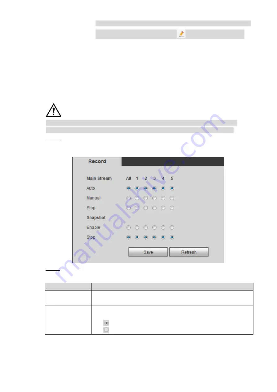
The Record interface is displayed, see Figure 5-15. 

 Record 

Figure 5-15


  Configure TCP/IP parameters. For details, see Table 5-5. 

Step 2

Table 5-5 Record control parameter description 

Name 

Description 

Channel 

Displays the channel number 

You can select one or several channels or select 

All


Status 

Indicates the recording status of corresponding channels. The choices 

include Auto, Manual, Enable, and Stop 


: Selected 


: Not selected 

Summary of Contents for MNVR4104 Series

Page 1: ...Mobile Network Video Recorder User s Manual V1 0 0 ...

Page 2: ...guide may cause harmful interference to radio communication For class A device these limits are designed to provide reasonable protection against harmful interference in a commercial environment Operation of this equipment in a residential area is likely to cause harmful interference in which case the user will be required to correct the interference at his own expense For class B device these lim...

Page 3: ... be changed to any set of numbers between 1025 65535 Avoiding the default ports reduces the risk of outsiders being able to guess which ports you are using 3 Enable HTTPS SSL Set up an SSL Certificate to enable HTTPS This will encrypt all communication between your devices and recorder 4 Enable IP Filter Enabling your IP filter will prevent everyone except those with specified IP addresses from ac...

Page 4: ...ng SNMP you should do so only temporarily for tracing and testing purposes only 12 Multicast Multicast is used to share video streams between two recorders Currently there are no known issues involving Multicast but if you are not using this feature deactivation can enhance your network security 13 Check the Log If you suspect that someone has gained unauthorized access to your system you can chec...

Page 5: ...ou time NOTE Provides additional information as the emphasis and supplement to the text Terms To simplify descriptions frequently cited functions and names in this manual have the following meanings Unless otherwise specified Device in this manual particularly refers to MNVR4104 series or MNVR4208 series products Remote devices in this manual refer to NVR IPC speed domes connected with the devices...

Page 6: ...t expose the Device to water or excessive moisture when washing the car A failure to follow this instruction might result in short circuit fire or other malfunctions The dust on the circuit board will cause short circuit which affect the normal operation of the Device and even damage the Device To make the Device work stably for a long time please regularly use the brush to remove the dust from co...

Page 7: ... all external wiring parts After all the lines connections are completed you can start connecting power cable Ensure the project is well grounded to avoid interference to video and audio signals and avoid electrostatic or induced voltage to damage the Device Unplug the power cable before you remove the audio video signal cable RS 232 or RS 485 cable otherwise these ports might be damaged ...

Page 8: ...4 Fixing the Device 19 2 3 5 Connecting to Power Cables 20 Audio and Video Input and Output Connection 22 2 4 2 4 1 About audio and video input 22 2 4 2 About audio and video output 23 Alarm Input and Output Connection 24 2 5 2 5 1 Alarm Input Type 24 2 5 2 Alarm Input Port 25 3 Boot up the Device 26 4 Local Configurations 27 Initializing Device 27 4 1 Logging into the Device 29 4 2 Quick Configur...

Page 9: ...Maintenance 117 4 8 2 Maintaining password 117 4 8 3 Querying log 120 4 8 4 Review status information 121 4 8 5 Auto Maintain 123 4 8 6 Backing Up and Restoring 125 4 8 7 Restored to the Default Settings 127 4 8 8 Network packet capturing 128 4 8 9 Shutdown 128 5 Web Operations 130 Initializing Device 130 5 1 Logging into the Device 131 5 2 Quick configuring 132 5 3 5 3 1 Configure IP address 132 ...

Page 10: ...ystem Firmwares 208 System Maintenance 208 5 7 5 7 1 Requirement for Maintenance 208 5 7 2 System Information 209 5 7 3 Auto Maintain 210 5 7 4 Backing Up and Restoring 212 5 7 5 Network packet capturing 214 6 Operating by DSS 215 7 FAQ 216 Mouse Operations 220 Appendix 1 HDD Capacity Calculation 222 Appendix 2 Technical Parameters 223 Appendix 3 ...

Page 11: ...nagement patrol cash carriers hazardous goods transport and logistics transport or video monitoring in harsh environments Functions 1 2 Function Description Storage Stores the data in the dedicated format which cannot be falsified and ensure the data security Compression Supports multi channel audio and video signals and each channel signal supports real time compression by independent hardware to...

Page 12: ...asted Satellite positioning Supports positioning function and recording linkage Recording search can be linked with vehicle moving track 3G 4G Wi Fi networks Adopts the latest wireless communication technology which has improved the manageability of the Device Removable HDD The extractable and seismic design make you lock and move the HDD easily to realize data backup Just connect the removable HD...

Page 13: ...ies are complete against the packing list Instructions about front panel rear panel and labels The functions of indicator lights and ports are described in the later chapter of the Manual The labels on the Device are very important for our after sales service To ensure the after sales service keep the labels well and do not tear or throw away You need to provide the serial number of the product wh...

Page 14: ... Alarm status indicator The red light is always on when alarms occur and off when not 7 IR Receives infrared signal from remote control 8 GPS GPS status indicator Glows blue when GPS positioning is working properly and the indicator is off when GPS function is not enabled NOTE This function is supported on the Device with GPS positioning module 9 3G 3G status indicator Glows blue when 3G dial up i...

Page 15: ... port Connects to Wi Fi antenna and receives Wi Fi signals NOTE This function is supported on the Device with Wi Fi module 3 3G 4G antenna port Connects to 3G 4G antenna for receiving 3G 4G signals NOTE This function is supported on the Device with 3G 4G modules 4 VGA interface Outputs analog video data to the connected display with VGA port For details see VGA Port introduction 5 AV OUT port Conn...

Page 16: ... input output port grounding and 12V output port For details see 2 5Alarm Input and Output Connection CAN port Used for data transfer between the Device and vehicle CAN network or other devices with CAN port A B Controls PTZ operations 11 Voice talk port Connects to voice talk device For details see Voice Talk Port introduction 12 EXTEND port See EXTEND Port introduction 13 HDMI interface Used to ...

Page 17: ...0 VGA line sync 3 VGA_G 7 VGA_R 4 RXD_232 8 TXD_232 2 2 3 3 EXTEND port EXTEND port Figure 2 6 Name Function 5 USB 5V upper line 5 USB 5V upper line USB data and USB data that connect to USB port IR Remote control signal indicator Receives signals from remote control 12 12V 1A output Ground VO AV video output RX RS 232 serial port sender and receiver that connects to RS 232 port TX ...

Page 18: ...t can connect to microphone Mic Out that can connect to earphone SPK Speak positive pole SPK Speak negative pole 2 2 3 5 AV OUT port AV OUT port Figure 2 8 Name Function 1 12V 1A output 2 Ground line 3 Audio output 4 Video Output 2 2 3 6 RS 232 interface RS 232 interface Figure 2 9 Name Function 1 12V 1A output 2 Ground line ...

Page 19: ...Dimension and Installation 9 Name Function 3 RXD_232 4 TXD_232 2 2 4 Dimensional drawing MNVR4104 structural and dimensional drawing Unit mm Figure 2 10 ...

Page 20: ...Dimension and Installation 10 MNVR4208 structural and dimensional drawing Unit mm Figure 2 11 ...

Page 21: ...s disconnected from power and do not plug or unplug components when the power is connected When installing and taking out HDD the Device electronic lock must be in unlocked status After the installation is complete the Device electronic lock must be in locked status before powering on the Device 2 3 1 Installing HDD 2 3 1 1 MNVR4104 series MNVR4104 series devices only support single HDD Gently pre...

Page 22: ...he front panel and take out the HDD carrier along the guide Step 3 rail Take out the HDD carrier single HDD Figure 2 14 Loosen two screws on the back panel of the HDD carrier take out the rear carrier panel Step 4 and remove the HDD carrier enclosure Remove the HDD carrier cover single HDD Figure 2 15 ...

Page 23: ...r screws to fix the HDD and HDD holder and install the HDD holder back to the Step 6 Device Installing HDD single HDD Figure 2 17 Install the HDD carrier enclosure in place along the rails and then fix the HDD Step 7 enclosure rear panel with two screws Place the HDD carrier back to the Device tighten two screws and close the door lock Step 8 ...

Page 24: ... key to unlock the door Step 2 Open door lock switch dual HDDs Figure 2 18 Loosen the two screws at the front panel and take out the HDD carrier along the guide Step 3 rail Take out the HDD carrier dual HDDs Figure 2 19 Loosen two screws on the back panel of the HDD carrier take out the rear carrier panel Step 4 and remove the HDD carrier enclosure Remove the HDD carrier dual HDDs Figure 2 20 ...

Page 25: ...screws to fix each HDD and the HDD holder and install the HDD holder back Step 6 to the Device Fix the upper HDD to the top of the HDD holder and the lower HDD to the side of the HDD holder Installing HDD dual HDDs Figure 2 22 Install the HDD carrier enclosure in place along the rails and then fix the HDD Step 7 enclosure rear panel with two screws ...

Page 26: ...is opened Steps The SIM card slot and SD card slot are inside the Device Gently press the left front cover Step 1 The left front cover automatically opens Use a particular key to unlock the door Step 2 Loosen the two screws at the front panel and take out the HDD carrier along the guide Step 3 rail Positions of the SIM card slot and SD card slot are shown in Figure 2 23 Insert the SD card and SIM ...

Page 27: ...llustrate the installation steps of locating antennas The installation process of other locating antenna is identical 2 3 3 2 1 Outside Installation Place the GPS antenna on the left front of the roof See Figure 2 25 Step 1 The antenna is magnetically attached to the roof of the vehicle Glue can be applied to four sides of the antenna to fix more reliably NOTE To make the sensitivity and accuracy ...

Page 28: ...roof and wiring requirements the antenna can be installed inside the vehicle To select the installation place it is recommended to place the antenna horizontally on the dashboard close to the windshield and make the GPS cable facing upward to enhance the signal as shown in Figure 2 26 Inside Installation Figure 2 26 ...

Page 29: ...ace washers onto the fixing screw 2 Use fixing screws with washers mount lugs to the bottom of the Device respectively and tighten the lugs Install the lugs onto the Device Figure 2 27 Fix the device onto the vehicle Step 2 1 Punch holes on the vehicle according to the installation dimensional drawing 2 Use screws to fix the Device onto the vehicle Fix the Device onto the vehicle Figure 2 28 Conne...

Page 30: ... live The black one is the grounding cable The orange one is the ACC signal Key live Power cable Figure 2 29 2 3 5 2 Obtain Connection Modes of the Main Power Switch In order to ensure correct cable connection it is necessary to obtain the connection mode of the main power switch through three methods is the main power switch connected to the positive or negative pole of the battery Ask the vehicl...

Page 31: ... the multimeter detects voltage remove the car key If the voltage changes to 0V it means that the measured signal is ACC on the car Turn off the main power switch on the vehicle and place the key in the OFF state Step 3 Connect the power cable according to the main power switch installation mode See Step 4 Figure 2 30 and Figure 2 31 CAUTION Before connecting with power cord select proper fuse 7 5...

Page 32: ...gh RJ45 network port When connecting cable the waterproof connector needs to be installed Take out the waterproof connector from the accessory box and connect the gasket Step 5 toward the arrow direction onto the waterproof connector See Figure 2 32 Gasket installation Figure 2 32 Put the network cable without Ethernet port through the main part of waterproof Step 6 connector gasket and encap and ...

Page 33: ...imultaneous output from these two ports Read the following contents carefully before using the computer instead of monitor For VGA output you need to prepare a VGA adapter cable to connect to computer To extend the Device life do not keep the Device running for a long time Regular demagnetizing helps keep the monitor working properly Stay away from devices with strong electromagnetic interference ...

Page 34: ...r Connection The common ground must be prepared for PTZ decoder and the Device otherwise the common mode voltage might not be able to control the PTZ It is recommended to use shielded twisted pair and the shielding layer can be used for common ground Prevent interference from high voltage power make reasonable wiring and take measures for lighting protection Parallel connect 120Ω resistance to red...

Page 35: ... control A B RS 485 port that connects to speed dome with PTZ function 2 5 2 Alarm Input Port Both NO and NC are supported The GND of alarm detector is in parallel connection with COM the power supply of alarm detector should be from external power source See Figure 2 38 The GND of alarm detector is in parallel connection with GND of Device Connect the NC port of alarm detector to the alarm input ...

Page 36: ...sure the Device works stably and prolong its service life In the first power on the Device needs connection to the ACC to work as intended Rotate the Device key to and rotate the vehicle key to ACC position The power indicator is on and the Device is ready for work NOTE For the first boot up or after restoring to the default factory settings the initialization interface is displayed on the screen ...

Page 37: ...evice 4 1 Plug the device s power line into a socket Step 1 After the Device is turned on the initialization interface is displayed See Figure 4 1 Device Initialization Figure 4 1 Enter the password confirm the password and the password hint and then click Step 2 Next The unlock pattern setting interface is displayed See Figure 4 2 NOTE To security your account it is recommended to keep the passwo...

Page 38: ...ction Figure 4 3 Configure the protection method for password If you do not want to set the protection Step 4 clear both the Reserved Phone Number check box and the Security Question check box Select Reserved Phone Number and enter the phone number The phone number must be 11 digit number and can be normally communicated Select the Security Question check box select the question and enter the corr...

Page 39: ...is displayed Then select Main Step 2 Menu The SYSTEM LOGIN interface is displayed See Figure 4 5 Logging in System Figure 4 5 NOTE If the unlock pattern was set during initializing the unlock pattern login interface is displayed Then use the unlock pattern to login Click to view the password hint to help you recall the password If the password is lost click and you can retrieve the password throug...

Page 40: ...nformation network connection remote device adding and recording schedule on the Device 4 3 1 Configure IP address According to the network planning configure the IP address of the Device and make sure the Device can connect to other devices in the network Connect the Device to the network and make sure the Device can communicate with other devices in the network diagram Preconditions Make sure th...

Page 41: ...DHCP When the DHCP function is enabled the system can automatically obtain the IP functions while IP Address Subnet Mask and Gateway cannot be configured You can check the current IP address whether the DHCP takes effect or not IP address According to your network plan enter the modified IP address gateway and subnet mask NOTE IP address and gateway must be in the same network segment Subnet Mask ...

Page 42: ...Table 4 2 Step 2 Table 4 2 General settings parameters description Name Description Language Select a language for the Device system Video standard Displays the video encode standard Auto Logout minute Enter the time period for automatic logout if there are no operations during this period In this case you need to login again The value ranges from 0 minutes through 60 minutes 0 indicates there is ...

Page 43: ...me Zone In the Timing Mode list if GPS or NTP is selected configure this parameter Configure the Time zone that the device is at Date format Select a date format Time format Select a time format Separator Separator style used for date DST The DST is applied in some countries or regions Select the DST check box if it is applied where the Device is located 1 Select the DST check box 2 According to t...

Page 44: ... Remote Devices Remote devices refer to IPC dome and other equipment that can be connected to the Device through network The system supports initialization remote device adding etc 4 3 3 1 Initializing the Remote Device Initializing the remote device includes configuration of login password and IP address for the remote device Add and operate a remote device after initialization of the remote devi...

Page 45: ...phone info check box The password setting interface is displayed 2 In the New Password box enter the new password and enter it again in the Confirm Password box Click Next The Password Protection interface is displayed 3 Set up password protection Select the Phone No check box and then enter the phone number Click Next Click Skip if you do not want to set up password protection The Network interfa...

Page 46: ...e manually or by search Different models of the Device support different number of remote devices to be added Add remote devices as needed Right click Remote Device on the main interface Step 1 The REMOTE interface is displayed Adding a remote device Step 2 Search and Add 1 Click Device Search the searched devices are displayed 2 Double click on an IP address or select the check box of a device an...

Page 47: ...fault setting is 80 HTTPS port Configure this parameter when the encryption function is enabled Enter HTTPs Port number of remote device The default setting is 430 Username Enter the user name and password to login to the remote device Password Remote Channel Select the channel number that you want to connect Encryption This parameter must be configured when you select Onvif as the Manufacturer En...

Page 48: ...chedule Manual Keep general recording for 24 hours for the selected channel Manual recording operation requires the user have the permission to access STORAGE settings Right click Manual Record on the homepage Step 1 The Record interface is displayed see Figure 4 12 Record Figure 4 12 Configure TCP IP parameters For details see Table 4 5 Step 2 Table 4 5 Record control parameter description Name D...

Page 49: ...Click Apply Step 3 4 3 5 Set up the storage plan Configure recording schedule and snapshot storage according to the actual application scenarios The Device starts corresponding types of recording and snapshot within a period of configured time 4 3 5 1 Configuring Recording Schedule The default recording setting is 24 hours general recording for all channels You can configure conducting various rec...

Page 50: ...d interface is displayed See Figure 4 14 Time Period Figure 4 14 2 Select the record type and weekday and enter the recording period 3 Click OK The recording schedule appears on the Record interface to view the configured recording schedule directly Click Apply Step 4 NOTE Click Copy to copy the settings to other channels 4 3 5 2 Configure snapshot schedule After snapshot schedule is configured th...

Page 51: ...responding to the week The Time Period interface is displayed See Figure 4 16 Time Period Figure 4 16 2 Select the snapshot type and weekday and enter the period for taking snapshot 3 Click OK Snapshot schedule appears on the Snapshot interface to view the configured snapshot schedule directly Click OK Step 7 ...

Page 52: ...r channel if needed You can view the information such as time channel name GPS and recording and alarm status in the channel view When you move the pointer to a channel window the live view control bar is displayed Click to display the channel window upside down with left and right side reversed The preview mode by default is general When the face detection is enabled right click Preview Mode Face...

Page 53: ... means no SIM card or no connection with a mobile network means the SIM card is installed and reflects signal strength Wireless network status Displays the Wi Fi and hotspot connection status The more the bars the stronger the signals means Wi Fi is available but not connected means the Wi Fi module does not exist indicates Wi Fi is connected and the strength of network signals means the hotspot i...

Page 54: ... layout mode Search Open the playback interface where you can search and play back record files or pictures PTZ PTZ Setting interface is displayed Remote Device Search and add a remote device Manual Record or Alarm Output interface is displayed Color Setting Color Setting interface is displayed Zero Ch Encode Zero Ch Encode interface is displayed NOTE After entering the main menu interface right c...

Page 55: ...n interface is displayed See Figure 4 20 PTZ Fn Figure 4 20 Configure parameters Step 2 Click Disable for Image De Jitter to enable the image de jitter function When enabled electronic image stabilization can be realized Click Disable for Defog to enable the defog function The system can automatically remove fog in video images to clearly display images in foggy and haze days Check Image NR and co...

Page 56: ...window screen The PTZ Shutter interface is displayed See Figure 4 21 PTZ Shutter Figure 4 21 Click Disable to enable the PTZ shutter Step 2 Click Save Step 3 4 4 1 3 4 Configuring PTZ Functions Click The PTZ function interface is displayed See Figure 4 22 SeeTable 4 8 for functions description PTZ Functions Figure 4 22 Table 4 8 PTZ Function Description Function Description ...

Page 57: ...value of the tour The value ranges from 1 255 3 Enter the preset value 4 Click Add Preset or Del Preset to add or delete the presets from the tour NOTE You can do this repeatedly to Add Preset or Del Preset from the tour Return to the PTZ function interface enter the tour value and then click The camera starts rotating according to the configured tour Click Del to delete the tour Touring pattern T...

Page 58: ...Click The camera PTZ will continuously rotate in a horizontal way by 360 degrees AUX Controls the screen wiper of external device through RS 485 command To use this function make sure it is supported on the external device Click to enable and disable light wiper or defogging Use the auxiliary command to enable power on setting or power off reset PTZ PTZ menu Click to enable the PTZ menu Operate an...

Page 59: ...r darkness Adjust the saturation according to the actual situation The bigger the value the lighter the color will become Hue Adjusts the image brightness Adjust the saturation according to the actual situation The bigger the value the brighter the image will become Sharpness Adjusts the edge sharpness of images The bigger the value is the more obvious the image edge will become Color mode Select ...

Page 60: ...ge is configured when an alarm event occurs the corresponding alarm output port generates alarm Stop After the alarm linkage is configured no matter whether there is an alarm event occurs the corresponding alarm output port never generate alarm Click Apply Step 3 View status of all alarm output ports under Status 4 4 1 6 Multi channel preview Right click Zero Ch Encode on the preview interface Ste...

Page 61: ...higher the video resolution the better the image quality FPS Configure the frames per seconds for video The larger the value is the smoother and more vivid the image will be Bit Stream Select a value for bit rate of video Click Apply Step 4 The zero ch encode icon is displayed on the Preview interface of the WEB screen 4 4 2 Video Search Right click Video Search on the preview interface The video ...

Page 62: ...o start fast play Audio Drag the slider to adjust the volume Click to enable mute mode Snapshot Click this icon to take a snapshot 4 4 2 2 Playing Back Recorded Video Files You can play back recorded video by time or file list During playing back you can zoom in an area of image to view the details To zoom in an area of image do either of the following Hold down the left mouse button to select the...

Page 63: ...ndancy HDD of the Device if it is supported Select the month year and channel number that you want to search Step 2 Select date and record type Step 3 Record Type Figure 4 27 Click to start playing back recorded video Step 4 4 4 2 2 2 Playing Back by File List The search sources include From R W HDD and redundancy HDD Step 1 The search sources include From R W HDD and redundancy HDD The redundancy...

Page 64: ...ing Back Snapshots You can play back snapshots by time or file list 4 4 2 3 1 Playing Back Snapshots by Time In the search type list select PIC Select where you want to search the snapshots Step 1 and enter the interval time The search sources include From R W HDD and redundancy HDD The redundancy HDD is supported only when there is a redundancy HDD on the Device For details about redundancy HDD o...

Page 65: ...ge Device From R W HDD Play back snapshots from local HDD of the Device From redundancy HDD Play back snapshots from redundancy HDD of the Device if it is supported Select the month year and channel number that you want to search Step 2 Select a date Step 3 Click Step 4 The snapshots are displayed in list See Figure 4 29 File list Figure 4 29 Set the start time and then click the searched snapshot...

Page 66: ...evice Select the external storage device and then click Switch To R W to transfer the external storage device to the record storage HDD The system automatically saves the recorded videos to the external storage device During backup click Stop to stop backing up Files backup Figure 4 30 Click Browse to select the storage path of recorded videos in an external storage Step 2 device Search recorded v...

Page 67: ...pe_Time dav The format for time is year month date hour minute second Alarm Configuration 4 5 4 5 1 Alarm After the arming and disarming period and the alarm linkage action are configured the system will start the corresponding linkage in the arming and disarming period Take the configuration of dynamic alarm linkage detection as an example The alarm linkage might be different depending on the ala...

Page 68: ...s only one alarm event After the delay motion detection is enabled motion detection begins after a period of time Set detecting area Step 4 1 Next to Region click Setup The Area interface is displayed see Figure 4 33 The monitoring image is divided to 22 18 PAL or 22 15 NTSC blocks PAL Phase Alteration Line applies to the countries and regions including China and Europe NTSC Nation Television Stan...

Page 69: ...elect the area of the image to be detected and set up its sensitivity and threshold value NOTE Channel alarm events As long as any one of the four regions triggers alarm the channel that houses the region will give alarm 4 Right click on the screen The DETECT interface is displayed Configure the alarm linkage SeeTable 4 12for details Step 5 Table 4 12 Description of Alarm Linkage Linkage Descripti...

Page 70: ...end Email When an alarm is triggered the system sends an alarm email to a designated recipient See4 5 1 7Sending for details Buzzer When an alarm is triggered the alarm buzzer beeps See4 5 1 8Buzzer for details System log When an alarm is triggered alarm message is recorded in the system log See4 5 1 9Log for details Click Save Step 6 4 5 1 2 Linking Recording After recording is linked the system ...

Page 71: ...ime Period interface is displayed See Figure 4 35 Time Period Figure 4 35 2 Select the record type and weekday and enter the recording period Configure the alarm type as needed and select Motion Detection or Alarm To configure video detection linking with alarm recording such as motion detection select Motion Detection To configure other types of alarm linking with recording such as local alarm se...

Page 72: ... recording channel starts alarm linking with recording Right click Manual Record on the homepage Step 5 The Record interface is displayed Enable automatic recording on the recording channel See Figure 4 36 Step 6 Record Figure 4 36 Click Apply Step 7 4 5 1 2 3 Configuring Recording Linkage In the alarm configuration interface configure alarm linking with recording and delay Enter the alarm configu...

Page 73: ...m video after type time channel number and record type are configured on the Playback interface 4 5 1 3 Linking Alarm Output After alarm output is linked the system gives an alarm by linking with the alarm output device when an alarm is triggered After an alarm ends the alarm stops after an extended time period according to the configured Alarm Delay Preconditions The Device has been connected to ...

Page 74: ... is triggered the alarm output device gives an alarm such as beep light flashing etc 4 5 1 4 Linking Snapshot After snapshot is linked the system starts snapshot by linking the channel when an alarm is triggered 4 5 1 4 1 Configure snapshot schedule After motion detection on channel or alarm snapshot plan is enabled the channel starts alarm linking with snapshot Select Storage Schedule Snapshot un...

Page 75: ...s displayed See Figure 4 40 Time Period Figure 4 40 2 Select the snapshot type and weekday and enter the period for taking snapshot Configure the alarm type as needed and select Motion Detection or Alarm To configure video detection linking with alarm video recording such as motion detection select Motion Detection To configure other types of alarm linking with video recording such as local alarm ...

Page 76: ...ter automatic snapshot on channel is enabled the channel starts alarm linking with snapshot Right click Manual Record on the homepage Step 1 The Record interface is displayed Enable the automatic snapshot on channel See Figure 4 41 Step 2 Record Figure 4 41 Click Apply Step 3 4 5 1 4 3 Configuring Snapshot Linkage Enter the alarm configuration interface and select Snapshot See Figure 4 42 Step 1 ...

Page 77: ...riggered enter the local Video Search interface After search condition is configured click the snapshot time period on the time shaft to play alarm snapshots back 4 5 1 5 Linking Tour After tour is linked a tour of the selected channels is displayed on the local interface of the Device when an alarm is triggered Steps Enter the alarm configuration interface and select Tour See Figure 4 43 Step 1 ...

Page 78: ...a tour of the selected channels is displayed on the local interface in a form of single window After an alarm ends the local interface returns to the window before alarm 4 5 1 6 Linking Message Show When an alarm is triggered alarm message is displayed on the local interface after message display is linked Steps Enter the alarm configuration interface and select Message Show See Figure 4 44 ...

Page 79: ...layed on the local interface of the Device 4 5 1 7 Linking Email Sending After Email sending is linked the system sends an alarm email to a designated recipient when an alarm is triggered 4 5 1 7 1 Configuring Email Settings The alarm linking with mail sending is effective only when the email address recipient and other information are configured Select NETWORK EMAIL Step 1 The EMAIL interface is ...

Page 80: ...l address You can enter up to three email addresses separated by colons Sender Select sender and configure email address Email Title You can enter no more than 63 characters in Chinese English and Arabic numerals Encrypt In the Encrypt list select an encryption type from NONE SSL and TLS Interval This is the interval that the system sends an email for the same type of alarm event which means the s...

Page 81: ... test if emails can be sent out and received as intended after configuration If the configuration is correct you would receive test email 4 5 1 7 2 Configuring Email Linkage Enter the alarm configuration interface and select Send Email See Figure 4 46 Mail sending Figure 4 46 4 5 1 7 3 Result Verification When an alarm is triggered the system sends an alarm email to a designated recipient 4 5 1 8 ...

Page 82: ...Verification When an alarm is triggered the Device beeps 4 5 1 9 Linking Log After log is linked alarm message is recorded in the system log when an alarm is triggered Steps Enter the alarm configuration interface and select System Log See Figure 4 48 ...

Page 83: ...tart time end time and researchable alarm log information See Figure 4 49 Alarm Log Figure 4 49 4 5 2 Configuring Video Detection Settings Check whether any change with a certain level occurs or not by analyzing video images If a change with a certain level occurs in an image such as object moving fuzzy image etc the system starts alarm linkage ...

Page 84: ...tampering Figure 4 50 Select the channel number and click to enable the tampering for the Step 2 channel Configure the sensitivity Step 3 The higher the sensitivity value is the easier the mobile object detection is triggered The possibility of false alarm also increases Configure the alarm linkage action See4 5 1Alarmfor details Step 4 Click Apply Step 5 4 5 3 Configuring Alarm Events Settings Co...

Page 85: ... default Select channel number and configure the alarm name Configure alarm event parameters Step 3 When the local alarm and the IPC offline alarm are enabled configure Anti dither and Device Type Anti dither After the anti dither time is configured the system records only one alarm event during this period Device type Select the device type of the external alarm device normally open and normally ...

Page 86: ...rm detection Configure abnormality parameters For the detailed description see Table 4 14 Step 4 Table 4 14 Abnormal event setting parameters description Name Description Attempt s If Illegal Login is selected configure this parameter In the Attempt s box enter the maximum number of allowed password input errors If the number of password input errors reaches this value the user account will be loc...

Page 87: ...linkage action See4 5 1Alarmfor details Step 5 When Restart System is enabled the system detects no HDD and restarts after 3 minutes Click Apply Step 6 4 5 5 Configuring Alarm Output Settings Configure the alarm port output type of the Device including auto manual and stop When the alarm output port is connected to the alarm device and alarm is linked with alarm output function configure the alarm...

Page 88: ...mation Step 1 The Alarm Information interface is displayed Configure type start time and end time Step 2 Click Search Step 3 The alarm information satisfying the searching conditions are displayed See Figure 4 54 To view detailed alarm information select it and click Details After the Device is connected to an external storage device click Backup to backup alarm information to the external storage...

Page 89: ...scription Name Description Record Type The record type is permanently fixed as general and cannot be changed For general record motion detection and alarm general stream is configured for recording Encode Mode Encode Mode of video Smart Code After the smart code is enabled reduce the bit rate value NOTE Only some models support Smart Code After the smart code is modified restart IPC Some IPC funct...

Page 90: ...to the reference bit rate and the bit rate changes along with the monitoring environment But the maximum bit rate value changes around the configured value Select Customized and you can configure bit rate value manually Quality This parameter can be set only when Stream Ctrl is set to BRC_VBR Select the image quality level The higher the value the better the image will become Bit Stream The system...

Page 91: ...d image If analog channel is selected select according to actual condition If digital channel is selected the resolution is the same with the main stream and cannot be modified Quality Configures the image quality by 6 levels Interval Interval of taking snapshots Select Customized to configure the snapshot interval for manually capturing snapshots The maximum value you can set is 3600 seconds as a...

Page 92: ...Review the connection status of the PoE port and reset the camera Select Camera PoE in the main menu The PoE interface is displayed See Figure 5 46 Click to turn on PoE reset function and click Apply to reset the camera with power but offline so that the camera can be online If the camera is still offline after reset for 3 times the system will not reset again When the total power of the cameras a...

Page 93: ...r simultaneous access to the device through Clients including WEB clients platform clients mobile phone clients etc Select Main Menu NETWORK CONNECTION SETTING Step 1 The Connection Setting interface is displayed See Figure 4 59 Port Figure 4 59 Configure the port parameters of the device For details see Table 4 17 Step 2 ...

Page 94: ...also available for Blackberry When the URL format requiring RTSP you need to specify channel number and bit stream type in the URL and also user name and password if needed When playing live view with Blackberry smart phone you need to turn off the audio and then set the code mode to H 264B and resolution to CIF URL format example Rtsp user name password IP address port cam realmonitor channel 1 s...

Page 95: ...ct Main Menu NETWORK WIFI Mode Switch Step 1 The Mode Switch interface is displayed See Figure 4 60 Mode switch Figure 4 60 Select the working mode Step 2 When the device needs to be connected to Wi Fi select WLAN as the working mode When the device needs to be used as a hotspot for other terminals select Hotspot as the working mode Click Apply Step 3 4 6 2 2 2 Configuring Wi Fi Network You can co...

Page 96: ...ly Add Wi Fi manually 1 Click Static Setting The Static Settings interface is displayed 2 Enter SSID and password select priority level and verification type set IP address subnet mask and gateway If you select the DHCP check box after successful connection the system automatically obtains the IP address subnet mask and gateway 3 Click Apply Result verification After successful connection you can ...

Page 97: ...ect work band and verification type and then Step 2 enter the connection password The work band can be 2 4G 5G Select the Connection Password check box the clear text password is displayed The default password is 12345678 Click Apply Step 3 4 6 2 3 Configuring 3G 4G Settings After setting 3G 4G parameters network status and data usage can be viewed 4 6 2 3 1 Setting 3G 4G Parameters Preconditions ...

Page 98: ...en enabled the network type is displayed which is used to distinguish the 3G 4G modules among Communication Operators such as TD LTE APN Displays access point of Communication Operator To manually set up APN select Customized AUTH Includes PAP CHAP and NO_AUTH protocols The system automatically recognizes and displays the enabled protocol Dial Number Enter the dial number provided from the Communi...

Page 99: ... 3G 4G 3G Flow The 3G Flow interface is displayed See Figure 4 65 The system displays data usage for the last 7 days and the total data usage of the month up to date The total data is zeroed out and accumulates again after a calendar month ends and a new one begins Click Refresh to obtain the latest updated flow information which is updated every 5 minutes Click Zero Out to clear all information o...

Page 100: ...onnected to the PoE port of the device CAUTION By default the Switch Settings check box is enabled The network segment is 10 1 1 1 It is recommended to keep the default setting If the IP camera is from the third party it must support the Onvif protocol and has enabled DHCP In the main menu select SYSTEM SETUP NETWORK SWITCH Step 1 The Switch interface is displayed See Figure 4 66 ...

Page 101: ...segment where the Switch is located Try to configure the IP address by arp ping If the DHCP function is enabled use DHCP to configure the IP address After the IP address is configured a broadcast will be sent from Switch If there is any response received the connection has been established Then you can login and find the IP camera You can find the corresponding digital channel has been occupied wi...

Page 102: ...ure 4 67 Net test Figure 4 67 In the Destination IP box enter the IP address and then click Test Step 2 After testing is completed the test result is displayed You can view the evaluation for average delay packet loss rate and network status 4 6 2 5 2 Testing Network Load You can view all the network information of the device such as MAC address connection status IP address data receiving speed an...

Page 103: ...ding speed and the red line represents data receiving speed 4 6 3 Configuring platform 4 6 3 1 Setting up auto registration After successfully auto registered when the device is connected into the Internet it will report the current location to the specified server to make it easier for the Client software to access the Device and to preview and monitor it Select PLATFORM REGISTER Step 1 The Auto ...

Page 104: ...me User name and password used for authentication when registering to the platform Password Click Apply Step 4 4 6 3 2 Configuring P2P Settings P2P is a private network penetration technology With this technology you do not need to apply for dynamic domain name set port mapping or deploy transit server You can add devices for management by either of the following two ways Download an app to your m...

Page 105: ...o add the device to DMSS Step 3 Client CAUTION Scan the QR code on the actual interface of Device Click OK Step 4 After configuration is complete the Status box shows Online meaning the P2P registration is successful Adding Device into Mobile Phone Client To use this function take adding device into mobile phone client as an example On your mobile phone download the application Step 1 After the in...

Page 106: ... Step 4 4 6 4 Setting Device Storage 4 6 4 1 Setting basic parameters In the main menu select Storage Management Basic Configuration Step 1 The Basic Configuration interface is displayed See Figure 4 71 Basic configuration Figure 4 71 Configure basic information Step 2 Select either to stop recording or overlap earlier recordings when HDD is full Set up the length for packaging recordings After co...

Page 107: ...to clear all data from the HDD Proceed with caution Disk management Figure 4 72 4 6 4 3 Setting FTP storage Back up recorded videos and images to the preset FTP File Transfer Protocol server for storage Preconditions Make sure you have purchased or download a FTP server and installed it on your PC NOTE For the created FTP user you need to set the write permission otherwise the upload of recorded v...

Page 108: ... if you want to login to the server anonymously Remote Directory Create folder on FTP server If you do not enter the name of remote directory the system automatically creates the folders according to the IP time and channel If you enter the name of remote directory the system creates the folder with the entered name under the FTP SFTP root directory first and then automatically creates the folders...

Page 109: ...1 1 2Configuring Snapshot Streaming Channel Select the channel that you want to apply the FTP settings Weekday Select the week day and set the time period that you want to upload the recorded files You can set two periods for each week Select the record type Alarm MD and General that you want to upload After checking the corresponding recording type next to the corresponding period the selected re...

Page 110: ...ou can manage the basic information of users and user groups To manage account easily it is recommended to give lower authority to the common user account than the advanced user account Authority In order to ensure the safety of the device operations in the ACCOUNT interface such as adding users deleting users etc can only be performed after the user s login password is correctly entered ...

Page 111: ...g the device may have different permissions You can group users of different levels to facilitate maintenance and management of user information Up to 64 user groups can be created in the system and the maximum length of user group names is 64 characters Admin and Onvif user groups are default in the system which cannot be deleted New user group can only be created under the root node Steps Select...

Page 112: ...rs numbers and special symbols including _ Remarks Setting up note info Click the System Playback or Monitor tabs respectively to set user group Step 4 permissions TIPS Select All to select all permissions under this category Click OK Step 5 Related Operations After adding user groups user group information can be edited and user groups can be deleted Refer to Table 4 23 for details Table 4 23 Rel...

Page 113: ...em user The system user is used to access and manage the device and the system default administrator is admin When adding different users ensure that users can only access resources within their own permissions Steps Select Main Menu SYSTEM ACCOUNT User Setup Step 1 The User Setup interface is displayed see Figure 4 78 User Figure 4 78 Click Add User Step 2 The system displays the Add User interfa...

Page 114: ... or more types from number letter and special characters excluding Enter a strong password according to the security level indication Confirm Pwd Remarks Enter a description of the user User MAC Binding the MAC address of the user PC accessing the device Group name Selecting the group to which users belong Click the System Playback or Real time Monitoring tabs respectively to set user Step 4 permi...

Page 115: ...users you need to log into the local interface to block online users first 4 6 5 3 Online User Select Main Menu STATUS NETWORK Online User the Online User interface is displayed See Figure 4 80 Set the blocking time and click to block online users Online User Figure 4 80 4 6 6 Set up system services The device supports setting up the startup and shutdown of various internal service functions of th...

Page 116: ...cal interface Make sure that the password protection question is set Mobile phone push When this function is enabled the device can push the triggered alarm snapshot to the mobile phone The system enables this function by default CGI When enabled the device can interface with other devices through CGI protocol The system enables this function by default Audio and Video Transmission Encryption When...

Page 117: ...utput Display Step 1 Output The Display Output interface is displayed See Figure 4 82 Display output Figure 4 82 Select resolution Step 2 Click Apply Step 3 4 6 7 2 Configuring tour parameters In the main menu select System Management Display Output Tour Step 1 The Tour interface is displayed see Figure 4 83 ...

Page 118: ...ion click Modify to modify the touring channels and touring sequence Select the check box of any channel group and then click Delete to delete the channel group Select the check box of any channel group and then click Up or Down to adjust the position of the channel group Click Apply Step 5 4 6 7 3 Adjust TV parameters In the main menu select System Management Display Output TV Step 1 Adjustment T...

Page 119: ...2 Click Apply Step 3 4 6 7 4 Configuring Video Mirror settings In the main menu select System Management Display Output Video Mirror Step 1 The Video Mirror interface is displayed See Figure 4 85 Video Mirror Figure 4 85 Select the channel and set up the mirror mode You can select left right mirror and Step 2 up down mirror Click Apply Step 3 ...

Page 120: ...ure TCP IP parameters For details see Table 4 27 Step 3 Table 4 27 Serial port parameter description Name Description Function Select the corresponding protocol Console Upgrades programs and debug by suing the serial interface and mini terminal software Vehicle lamp box An external vehicle lamp box can be connected RS485 External RS485 peripherals can be connected Baud rate The times of signal cha...

Page 121: ...ation mode Mileage Displays the total mileage Start Mileage Enter the initial mileage of the vehicle Speed source Select where the speed is obtained including Pulse Positioning Info and Pulse Positioning Info Pulse 1 Get the speed information from vehicle pulse system Positioning Info Get the speed information from positioning system Pulse Positioning Info Get the speed data from both the pulse sy...

Page 122: ... of Gyro parameters Name Description Type of vehicle head side axle Select the type of vehicle head side axle coordinates and the tilt angle of the slope Vehicle head side axles include X Y Z axles Only when the Vehicle Head Side Shaft is not Undetermined can the system detect the rapid acceleration and deceleration events of the vehicle Inclination angle of slope Unit Click Apply Step 3 4 6 9 3 C...

Page 123: ...le The system reports vehicle position to platform only if one of conditions is satisfied Report by Distance Inflexion Angle Report Interval When ACC off When the vehicle ACC status is off the system report the position to platform according to the configured report interval Platform schedule In the Report Strategy list select Platform Schedule The Platform Schedule setting interface is displayed ...

Page 124: ...rea you can view the resumed upload status after offline and resumed upload details Click DATA FORMAT to clear the resumed upload record System Update 4 7 4 7 1 Viewing system version Check the device model software version and other information Select Main Menu STATUS VERSION The VERSION interface is displayed See Figure 4 91 ...

Page 125: ...ersion by importing bin files Preconditions The correct version of the upgrade file has been obtained An external storage device USB flash drive etc with upgrade files has been inserted into the device Steps Select Main Menu SYSTEM UPGRADE Step 1 The Upgrade interface is displayed See Figure 4 92 ...

Page 126: ...ade type to start upgrade Step 2 Click System Upgrade to update the system Click MCU Update to update the MCU The Upgrade interface is displayed See Figure 4 93 System update 2 Figure 4 93 Select the upgrade file and then click Start Step 3 The system starts upgrading ...

Page 127: ...word every 3 months Check your system log regularly Handle problems asap Backup your configuration of system regularly Reboot this device regularly Upgrade firmwares regularly 4 8 2 Maintaining password 4 8 2 1 Change Password It is recommended that users modify their passwords regularly to improve the security of the device Select Main Menu SYSTEM ACCOUNT User Setup Step 1 The User Setup interfac...

Page 128: ...f other users Optional Set up a reserved mobile phone Step 5 Setting up a reserved phone number lets you reset the login password of the admin account if it was lost See4 8 2 2Reset Password Click OK Step 6 4 8 2 2 Reset Password You can reset the password through the reserved phone number when the password for the admin account is lost Preconditions The password reset function has been enabled an...

Page 129: ... is displayed See Figure 4 96 If you did not configure unlock pattern the password login interface is displayed See Figure 4 96 NOTE On the unlock pattern login interface click Switch User to login or on the password login interface in the User Name list select another user to login Login Figure 4 96 Click Step 2 The Message interface appears See Figure 4 97 Message Figure 4 97 Click OK Step 3 ...

Page 130: ... only be reset through the security question after the security question has been set Click Next Step 5 The Reset the password interface is displayed Reset and confirm the password Step 6 The new password can be set from 8 characters through 32 characters and contains at least two types from number letter and special characters excluding Enter a strong password according to the security level indi...

Page 131: ... 8 4 Review status information 4 8 4 1 Review running status You can review the running status of the device Select Information Running Status The system displays the ACC status voltage temperature and more See Figure 4 99 Running status Figure 4 99 ...

Page 132: ...longitude and search results Select Main Menu Status Information SATELLITE INFO The SATELLITE INFO interface is displayed See Figure 4 100 Satellite information Figure 4 100 4 8 4 3 Viewing alarm status You can view the alarm status The alarms of each channel are displayed in the alarm interface Select Main Menu STATUS ALARM The ALARM interface is displayed See Figure 4 101 ...

Page 133: ...a stream rate and diagram of data rate changes Select Main Menu STATUS BPS The BPS interface is displayed See Figure 4 102 Viewing Data Rate Information Figure 4 102 4 8 5 Auto Maintain You can configure the automatic maintenance settings such as auto reboot auto booting up or shutdown and delay for auto shutdown ...

Page 134: ...CC is disconnected the Device shuts down according to the settings of auto delay for shutdown If you enter the delay value that is not 0 the Device automatically shuts down after the preset delay If you enter 0 the Device shuts down according to the auto shutdown settings without delay Select Main Menu SYSTEM SYSTEM MAINTENANCE Step 1 The SYSTEM MAINTENANCE interface is displayed Configure the aut...

Page 135: ...the auto shutdown the Device is turned off immediately If the auto boot up is not set when the ACC is disconnected the Device shuts down at the scheduled time Select Main Menu SYSTEM SYSTEM MAINTENANCE Step 1 The SYSTEM MAINTENANCE interface is displayed In Auto Shutdown System select Everyday and then enter the specific time Step 2 Click OK Step 3 4 8 6 Backing Up and Restoring 4 8 6 1 Backing up...

Page 136: ...CONFIGURE BACKUP Step 1 The CONFIGURE BACKUP interface is displayed If the external storage device is connected before the interface is entered the system will automatically identify the information of the external storage device as shown in Figure 4 105 If the external storage device is connected after the interface is entered click Refresh and the system will recognize the connected external sto...

Page 137: ...AULT Step 1 The DEFAULT interface is displayed See Figure 4 106 Restored to the Default Settings Figure 4 106 Select the check box of the options that you want to restore to the factory default Step 2 Default Select the options and then click Default In the pop up message click OK The selected options will be restored to the factory default settings Restore the factory settings Click Restore the f...

Page 138: ...rface is displayed 2 Select the packet NOTE Click Refresh to refresh the total space free space and device file list When the capacity is insufficient click to delete the unnecessary files to release the capacity Click New Folder to create a new folder in the external storage device 3 Click OK Test NET TEST interface is displayed Click to start backing up packet Step 4 NOTE The packet of only one ...

Page 139: ...Local Configurations 129 Click Manual Reboot and the device is rebooted immediately Click Logout User to log out the currently logged in user Shutdown Figure 4 107 ...

Page 140: ...allowed your system to be restored the factory settings you need to initialize the device Only after that can you operate and configure your device Preconditions Please make sure the correct network connection between PC and the Device Steps Open the browser enter the Device IP address the default IP address is Step 1 192 168 1 108 and then press Enter The password setting interface is displayed S...

Page 141: ...er in the box Check the Security Question box select the question and enter the corresponding answer Click Next Step 4 The completion interface is displayed See Figure 5 3 Complete Figure 5 3 Click Save Step 5 Logging into the Device 5 2 You can login to and then configure the device Open the browser enter the Device IP address and then press Enter Step 1 The Login interface is displayed See Figur...

Page 142: ... for initial login In the upper left corner the main stream and substream are differentiated by the tab For admin account if you forget password click Forgot Password to find back the password For details see 5 5 5 3 3Reset Password Preview interface Figure 5 5 Quick configuring 5 3 5 3 1 Configure IP address Connect the Device to the network and make sure the Device can communicate with other dev...

Page 143: ...pported NOTE For IPv6 version in the IP address box Default Gateway box Preferred DNS box and Alternate DNS box enter 128 bits and cannot be blank MAC address Host s MAC address cannot be modified Mode Static You need to manually configure IP Address Subnet Mask and Default Gateway DHCP Obtains IP address automatically With DHCP enabled IP Address Subnet Mask and Default Gateway cannot be configur...

Page 144: ...e basic settings including time and date settings 5 3 2 1 Setting General Information Set up the general information of the Device including video recording strategy when the HDD is full recording length menu standby duration license plate and more Select SETUP SYSTEM GENERAL General Step 1 The General interface is displayed see Figure 5 7 General Figure 5 7 Configure TCP IP parameters For details...

Page 145: ...nutes through 60 minutes 0 indicates there is not standby time for the Device Startup Wizard Set whether to open the software license agreement License No Enter the license plate number of vehicle where the Device is located IPC Time Sync You can select the IPC Time Sync check box and enter the interval for IPC sync with the Device Click Save Step 3 5 3 2 2 Date and Time Settings You can configure...

Page 146: ...r In the Timing Mode list if NTP is selected configure this parameter After configuring NTP server the Device syncs time with NTP server 1 In the Timing Mode list select NTP to enable the NTP timing function 2 Configure parameters Server Enter IP address of NTP server Synchronize Click Synchronize to sync the Device time with NTP server Port The system supports TCP protocol only and the default se...

Page 147: ...layed Select the check box the uninitialized device and then click Initialize Step 4 The password setting interface is displayed See Figure 5 10 Password setting Figure 5 10 Configure the password by either of the following two ways Step 5 Using current device password and phone info Select the Using current device password and phone info check box and the remote device uses the password and phone...

Page 148: ... 5 11 2 In the New Password box enter the new password and enter it again in the Confirm Password box Click Next The password protection interface is displayed See Figure 5 12 Password protection Figure 5 12 3 Set up password protection Select the Phone No check box and then enter the phone number Click Next Click Skip if you do not want to set up password protection ...

Page 149: ... device manually or by search Select Setup CAMERA REMOTE Step 1 The REMOTE interface is displayed Adding a remote device Step 2 Search and Add 1 Click Device Search the searched devices are displayed 2 Double click on an IP address or select the check box of a device and then click Add The device displays in the added device area Manual Add 1 Click Manual Add The Manual Add interface is displayed ...

Page 150: ...The default setting is 554 HTTP Port Enter HTTP Port number of remote device The default setting is 80 Username Enter the user name and password to login to the remote device Password Remote Channel Select the channel number that you want to connect Channel The channel number of the remotely connected device You can only select a channel that has not added remote devices Decode buffer Enter the si...

Page 151: ... 24 hours for the selected channel CAUTION Manual recording operation requires the user have the permission to access STORAGE settings Check to ensure the HDD installed in the Device has been formatted properly Select Setup Storage Record Step 1 The Record interface is displayed see Figure 5 15 Record Figure 5 15 Configure TCP IP parameters For details see Table 5 5 Step 2 Table 5 5 Record control...

Page 152: ...op Do not record Enable Stop Enable or disable the scheduled snapshot for the corresponding channels Click Save Step 3 5 3 5 Set up the storage plan 5 3 5 1 Configuring Recording Schedule The default recording setting is 24 hours recording for all channels You can configure the record type and recording time according to your actual situation Preconditions The auto recording is enabled for the cor...

Page 153: ...rd Start recording for 0 seconds to 30 seconds before the alarm event occurs If you enter 0 seconds there will be no pre recording Configure the recording time period Step 3 1 Click Setup corresponding to the week The Settings interface is displayed See Figure 5 17 Settings Figure 5 17 2 Select the record type and weekday and enter the recording period NOTE If the MD check box and the Alarm check ...

Page 154: ... to other channels 5 3 5 2 Configure snapshot schedule You can configure the storage schedule for taking the snapshot Preconditions The Snapshot is enabled for the corresponding channel For details see 5 3 4 Configuring Record Settings Steps Select Setup Storage Management Storage Plan Snapshot Step 1 The Snapshot interface is displayed See Figure 5 18 Snapshot Figure 5 18 Configuring time period ...

Page 155: ...Snapshot interface to view the configured snapshot schedule directly Click Save Step 3 Common operations 5 4 5 4 1 Live View After you logged in the web interface the PREVIEW interface is displayed See Figure 5 20 Preview interface Figure 5 20 Table 5 7 Preview interface parameters description me Description em u Includes PREVIEW PLAYBACK ALARM SETUP INFO and LOGOUT ...

Page 156: ...k to Auto NOTE This function is only supported by main stream al back Plays back the video file dav stored on the PC Click Local Playback select the video file in the pop up dialog box and then click Open to start playing back the video file dow tion ations Configure the image quality playback fluency full screen vertical sync and window split mode For real time monitoring you can select the fluen...

Page 157: ...st PTZ support rotating device toward eight directions up down Left right left up right up left down right down Speed function controls the movement speed For example the rotation with the step length at 8 is faster than the rotation with the step length at 1 Click to display or hide the PTZ settings and PTZ menu functions PTZ Console Figure 5 21 5 4 1 1 1 PTZ You can configure scan preset tour pa...

Page 158: ... its live video on the screen See Figure 5 25 Video monitoring screen Figure 5 25 Table 5 11 Video monitoring window parameters description No Parameter Description 1 4 Device information Displays the IP address channel number bit stream and stream type M represents main stream S represents sub stream 5 Area zoom in Click this icon and then hold down the left mouse button to select the area you wa...

Page 159: ...encode settings the monitoring does not give sound 9 Close Close the live view in the window Bit rate The system supports switching between main stream and sub stream in real time monitoring window See Figure 5 26 For details about stream settings see 5 5 1 2Configuring encode parameters Bit rate Figure 5 26 5 4 1 2 Voice intercom You can do the two way voice talk between the Device and Client Voi...

Page 160: ...t PTZ support rotating device toward eight directions up down Left right left up right up left down right down Speed function controls the movement speed For example the rotation with the step length at 8 is faster than the rotation with the step length at 1 Click to display or hide the PTZ settings and PTZ menu functions PTZ Console Figure 5 28 5 4 1 3 2 PTZ You can configure scan preset tour pat...

Page 161: ...onfiguration In the PTZ Setup list select Preset and then move the camera to the direction that you want to monitor 9 Click Preset and control the PTZ console to turn the camera to the target monitoring direction 10 In the Preset box enter the preset value 11 Click Add to complete adding preset 12 In the Preset box enter the preset value and then click Go to the camera moves to the location of pre...

Page 162: ...ck Light Click On to turn on the light and click Off to turn off the light Wiper Controls the screen wiper of external device through RS 485 command To use this function make sure it is supported on the external device In the PTZ Setup list Click Screen Wiper Click On to turn on the screen wiper and click Off to turn off the screen wiper Clear fog Controls the warming up module of external device ...

Page 163: ...he monitoring screen Table 5 14 OSD menu parameters description Parameter Description Camera Move the pointer to Camera and then click Save to enter the sub menu of Camera You can configure the camera parameters such as image exposure backlight white balance day night zoom and focus PTZ Move the pointer to PTZ Setup and then click Save to enter the sub menu of PTZ Setup You can configure the PTZ p...

Page 164: ...n Brightness Adjusts the image brightness The bigger the value is the brighter the image will become Contrast Adjusts the contrast of the images The bigger the value is the more obvious the contrast between the light area and dark area will become Saturation Adjusts the color darkness Adjust the saturation according to the actual situation The bigger the value the lighter the color will become Hue...

Page 165: ...w is enabled the output image is compressed to combine multiple channels in the local interface to one channel Then you can view multiple channels from remote access and save much of the network transmission bandwidth Select a channel and then select the split mode from Then you can view the multiple channel views in one channel See Figure 5 33 Multi channel preview Figure 5 33 5 4 2 Video playbac...

Page 166: ...n be adjusted 4 Sync If the playback time of other channels is before the time of the selected channel then other channels will speed up playback till sync with the selected channel If the playback time of other channels is after the time of the selected channel then other channels will pause to wait till synced with the selected channel If the playback time of other channels is after the time of ...

Page 167: ...or not being played click this icon to play video Stop Click this icon to stop playback Previous frame Click this icon to jump to the previous frame NOTE You need to pause the playback before using play by frame Next frame Click this icon to play the next frame NOTE You need to pause the playback before using play by frame Fast playback and slow playback Move the slider to adjust the playback spee...

Page 168: ...nel and then select the record type Record Type Figure 5 35 Click to start playing back recorded video Step 3 5 4 2 2 2 Playing Back Recorded Video by File List Select the month and year that you want to search and then select the screen split Step 1 layout and enter the corresponding channel number Select a date with recorded video files click on the window channel to select a Step 2 playback cha...

Page 169: ...t the channel number Step 2 Clip the recorded video by either of the following ways Step 3 Click and the and sliders appear at the two ends of the time axle Move the sliders to the proper location and then click to clip and save the section between the sliders In the clip box enter the start time and end time and then click to clip and save the section in this period Clip and save Figure 5 37 The ...

Page 170: ... The Download to Local interface is displayed Select the record type and save path Step 4 Downloaded video formats supported by the system include DVA and MP4 Choose according to the actual situation Click Save Step 5 The system indicates the downloading progress and pops up a message after completed 5 4 2 4 2 Download by time You can download the recorded video by time Click the Download by Time ...

Page 171: ...ystem indicates the downloading progress and pops up a message after completed 5 4 2 4 3 Watermark You can also verify whether the watermark is falsified Click the Watermark tab Step 1 The Watermark interface is displayed See Figure 5 40 Watermark Figure 5 40 Click Local File and select a file that you want to verify Step 2 Click Verify Step 3 The system indicates the verifying progress and result...

Page 172: ...ts settings Video tampering The alarm is triggered when the camera lens is covered The tampering function is enabled For details see 5 5 3 1 2 Configuring Tampering Settings Disk error The alarm is triggered when the HDD has failures or malfunctions The HDD error detect function is enabled For details see 5 5 3 3 Abnormality Video loss The alarm is triggered when video loss occurs Disk full The al...

Page 173: ... be played Step 4 when an alarm is triggered 1 Select the Play Alarm Sound 2 Click Select to select the alarm sound file System Settings 5 5 NOTE In this section when you have configured the settings for a channel click Copy to apply the configurations to other channels Click Refresh to display the latest configuration Click Default to restore to factory default settings 5 5 1 Configuring lens par...

Page 174: ...h linear mode The bigger the value is the brighter the image will become Contrast Adjusts the contrast of the images The bigger the value is the more obvious the contrast between the light area and dark area will become Sharpness Adjusts the edge sharpness of images The bigger the value is the more obvious the image edge will become 3D NR Reduces the noises of multiple frame at least two frames im...

Page 175: ...or temperatures in the environment accordingly Day Night You can select device display mode from color or black and white mode You can select Auto Black and White and Colored NOTE Day Night configuration is independent from profile management configuration Colored The camera displays colored images Auto The system switches between color and black and white display according to the actual condition...

Page 176: ...moother and more vivid the image Stream Ctrl You can select bit rate type CBR Constant Bit Rate which changes around the configured value VBR Variable Bit Rate which changes along with environment NOTE It is recommended to select CBR when there might be only small changes in the monitoring environment and select VBR when there might be big changes in the monitoring environment Bit Rate Configure t...

Page 177: ... video is falsified Watermark String Enter the strings for verifying watermark The default string is DigitalCCTV The watermark string can only consist of number letter underline _ and strikethrough and maximum length contains 127 characters Click Save Step 4 5 5 1 2 2 Configuring Snapshot Settings You can configure the snapshot settings such as snapshot type image size quality and interval Select ...

Page 178: ...y interface is displayed See Figure 5 46 Overlay Figure 5 46 Select a channel Step 2 Sets up DBHA parameters See Table 5 22 for details Step 3 Table 5 22 Overlay settings parameters description Name Description Period Title Select the Time Display check box the Setup button is displayed Then click Setup the time is displayed on the channel window and then drag it to a proper location Channel Title...

Page 179: ...ave path for snapshots and records Step 2 On the PREVIEW interface images and recordings taken by snapshot and recording are saved in the following paths by default Default paths C PictureDownload and C RecordDownload Click Save Step 3 5 5 1 3 Configuring Channel Name You can configure the channel name for the corresponding device Select SETUP CAMERA CHANNEL NAME Step 1 The CHANNEL NAME interface ...

Page 180: ...ent Figure 5 49 5 5 2 Network Parameters Configuration Set up the network parameters of the device as needed This includes setting up the port Wi Fi parameters 3G 4G parameters Email FTP active registration P2P and SWITCH 5 5 2 1 Connection Setting Configure the maximum port numbers and values Select Setup Network Connection Setting Step 1 The Connection Setting interface is displayed See Figure 5...

Page 181: ...the code mode to H 264B and resolution to CIF URL format example Rtsp user name password IP address port cam realmonitor channel 1 subtype 0 Username such as admin Password For example admin_123 IP address For example 192 168 1 16 Port The default setting is 554 If the default setting is displayed you do not need to configure this parameter Channel Refers to the Channel number starting from 1 For ...

Page 182: ...odule Steps Select Setup Network WIFI Step 1 The WIFI interface is displayed Select Wifi as the working mode Step 2 The WIFI configuration interface is displayed See Figure 5 51 Wi Fi Figure 5 51 Connect to Wi Fi Step 3 Auto search 1 Click Search SSID In the SSID list all the available Wi Fi networks are listed including the information such as network name connect mode authorize mode and signal i...

Page 183: ...status After successful connection you can view the current hotspot IP address subnet mask and gateway in WIFI Working Info 5 5 2 2 2 Configuring Wi Fi Hotspot The Device can work as a hotspot to share the network connection to other terminals The terminals connected to the hotspot can login to the Device through IP address 192 168 2 108 After login you can preview videos on the Device Select Setu...

Page 184: ...e Communication Operator Steps Select Setup Network 3G Step 1 The CDMA GPRS Setup interface is displayed NOTE After 3G 4G module is connected the module information and wireless signal are displayed if not click Search to search for wireless signal Select 3G Network and Enable to open the network This function is enabled by Step 2 default Configure TCP IP parameters For details see Table 5 24 Step...

Page 185: ...r CHAP The system automatically recognizes the username and password Password Wireless network status After successful dial up all relevant information is displayed without any setup needed Such information includes module status SIM status dial up status working mode IMSI IMEI IP address subnet mask gateway and module number Wireless Signal Click Search to search for wireless signals Click Save S...

Page 186: ... port value of SMTP server Username Enter the user name and password of SMTP server Password Sender Sender s email address Encryption type In the Encrypt list select an encryption type from NONE SSL and TLS Title You can enter no more than 63 characters in Chinese English and Arabic numerals Attachment Select Attachment When an alarm takes place the system can send alarm linkage and take snapshots...

Page 187: ... the connection after the specified interval NOTE The value ranges from 30 minutes to 1440 minutes Email Test Click Email Test to test if emails can be sent out and received as intended If the configuration is correct you would receive test email Before testing click Save to save the email settings Click Save Step 4 5 5 2 5 Configuring FTP Settings Back up recorded videos and images to the preset ...

Page 188: ...the PC that is installed with the FTP SFTP server Port The default value is 21 Username The username and password used to access the server Password Anonymous Select Anonymous if you want to login to the server anonymously Remote Directory Create folder on FTP server If you do not enter the name of remote directory the system automatically creates the folders according to the IP time and channel I...

Page 189: ...hot every 10 seconds When the Snap Mode is Event the system uploads captured pictures according to snapshot interval NOTE You can configure the Snap Interval and Snap Mode For details see 5 5 1 2 2Configuring Snapshot Settings Channel Select the channel that you want to apply the FTP settings Weekday Select the week day and set the time period that you want to upload the recorded files You can set...

Page 190: ...work penetration technology With this technology you do not need to apply for dynamic domain name set port mapping or deploy transit server You can add devices for management by either of the following two ways Download an app to your mobile phone by scanning the QR code on the interface by using mobile phone client and sign up an account see Client Operation Examples Loginwww gotop2p complatform ...

Page 191: ...he Status box shows Online meaning the P2P registration is successful Adding Device into Mobile Phone Client To use this function take adding device into mobile phone client as an example On your mobile phone download the application Step 1 After the installation run the client select Remote Monitoring and go to the main Step 2 menu Add the device to the mobile client Step 3 1 Click and then selec...

Page 192: ...fter scanning the device is added The serial number of the device is displayed in Serial Number section To review the monitoring image of the device click Start Preview Step 4 5 5 3 Set alarm information You can configure the alarm settings such as video detection alarm events abnormality and alarm output 5 5 3 1 Configuring Video Detection Settings Video detection includes motion detect and tampe...

Page 193: ...up Event Handling Video Detection Motion Detect Step 1 The Motion detection interface is displayed see Figure 5 59 Motion detection Figure 5 59 Select Enable and select target channels for dynamic detection Step 2 Region configuration Step 3 1 Click Setup after Region The Setup interface pops up See Figure 5 60 Motion detect region setup Figure 5 60 2 Select a region and set up the region name ...

Page 194: ... record channel s when an alarm event occurs the corresponding channel starts recording automatically NOTE Two more conditions must be satisfied before alarm recording function works Motion detection recording is enabled See 5 3 5 1Configuring Recording Schedule Auto recording is enabled See 5 3 4Configuring Record Settings Recording delay After an alarm finishes the alarm recording is extended fo...

Page 195: ...cause of the causes such as sunlight status the monitoring cannot be continued normally and in this case the system activates alarm and links the configured actions Select SETUP EVENT HANDLING VIDEO DETECTION TAMPERING Step 1 The Tampering interface is displayed See Figure 5 61 Video tampering Figure 5 61 Select Enable Channel and the target channel for video tampering detection Step 2 Sets up DBH...

Page 196: ...this parameter Normal Open The alarm signal is disconnected normally The alarm is activated when alarm signal is connected Normal Close The alarm signal is disconnected normally The alarm is canceled when alarm signal is disconnected Trigger If selecting Local Alarm as the Event Type configure this parameter If the alarm signal is 12V 24V voltage select High as the triggering mode if the alarm sig...

Page 197: ...starts capturing automatically NOTE You can also configure the frequency size and quality of snapshot For details see 5 5 1 2 2Configuring Snapshot Settings Show Message Select the Show Message check box to enable a pop up message in your local host PC when an alarm event occurs Buzzer Select the Buzzer check box to activate a buzzer noise at the device when an alarm event occurs Send Email Select...

Page 198: ... the Attempt s box enter the maximum number of allowed password input errors If the number of password input errors reaches this value the user account will be locked Lock Time If Illegal Login is selected configure this parameter Set up the lock time for the locked user account when the number of password input errors reaches this value Ceiling temperature If Temperature Too High is selected conf...

Page 199: ... Show Message Select the Show Message check box to enable a pop up message in your local host PC when an alarm event occurs Send Email Select Send email and when alarm is triggered the system sends email to the specified mailbox NOTE Set your e mail first before enabling this function See 5 5 2 4 Configuring Email Settings for detailed operations Buzzer Select the Buzzer check box to activate a bu...

Page 200: ...d write properties of HDD and review HDD capacity Select Setup Storage Management HDD Management The HDD Management interface is displayed See Figure 5 65 You can set up the HDD as the read write disk and redundancy HDD on the HDD Operation column Read Write Read HDD data and save data to HDD Redundancy HDD If more than two HDDs are connected to the device or SD card one HDD can be set to the redu...

Page 201: ...on including the output mode serial port parameters and user account management 5 5 5 1 Configuring Zero Ch Encode Settings You can configure the parameters such as compression mode resolution and frame rate for Zero Channel view Select Setup System Display Output Step 1 The Zero Ch Encode interface is displayed See Figure 5 68 ...

Page 202: ... resolution the better the image quality FPS Configure the frames per seconds for video The larger the value is the smoother and more vivid the image will be Bit Rate Select a value for bit rate of video Click Save Step 4 The zero ch encode icon is displayed on the PREVIEW interface For details see 5 4 1 5Multi channel preview 5 5 5 2 Configuring RS 232 Port Parameters You can configure the RS 232...

Page 203: ...a bit Select a data bit The options include 5 6 7 and 8 Stop bit Select a stop bit The options includes 1 1 5 and 2 Parity Select a parity mode from None Odd Even Mark and Null Click Save Step 3 5 5 5 3 Managing User Account You can add modify and delete user accounts and groups and configure security questions for admin account The Default User and Authority The default user account is admin The ...

Page 204: ...er number underline _ and hyphen 5 5 5 3 1 User Management You can add delete or modify user and set the authorities for the user of a group Add User Select Setting System Account User Step 1 The system displays the User interface See Figure 5 70 User Figure 5 70 Click Add User Step 2 The Add User interface is displayed See Figure 5 71 Add User Figure 5 71 Sets up DBHA parameters See Table 5 33 fo...

Page 205: ...unt authority it is recommended to give lower authority to the common user account than the advanced user account Authority Click Save Step 4 NOTE Click to modify user information click to delete the user Change Password On the User interface click Step 1 The Modify User interface appears See Figure 5 72 Change Password Figure 5 72 Select the Modify Password check box and then enter old password n...

Page 206: ...lost See 5 5 5 3 3Reset Password Click Save Step 4 NOTE The new password can be set from 8 characters through 32 characters and contains at least two types from number letter and special characters excluding Please enter a strong password according to the password strength indication A user authorized to manage user accounts can modify its own password and the passwords of other users 5 5 5 3 2 Gr...

Page 207: ... the corresponding group information click to delete the group 5 5 5 3 3 Reset Password You can reset the password through the reserved phone number when the password for the admin account is lost Open a browser and login the web interface of Device Step 1 The login interface is displayed Enter the username admin Step 2 The password setting information is displayed See Figure 5 75 ...

Page 208: ... Scan the QR code on the actual interface of Device You can get the security code twice by scanning the same QR code If you need to get the security code once again please refresh the interface The security code is valid for 24 hours Wrong security code entrance up to five times will cause the admin account locked for five minutes In the security code box enter the security code received in your r...

Page 209: ...Please set a high security password according to the prompt of password strength Click Save Step 9 The system prompts successful operation You can use the new password to login to the device 5 5 5 3 4 Online User Review online user information Select INFO INFO ONLINEUSES the Online User interface is displayed See Figure 5 78 Online User Figure 5 78 5 5 6 Safety 5 5 6 1 Set up system services Selec...

Page 210: ...oftware shall support video decryption Click Save Step 3 5 5 6 2 HTTPS Settings Through creating server certificate or downloading root certificate and setting port number the PC can login the Device by HTTPS to ensure the security of communication data and guard the users information and device security with stable technology measure Preconditions On the Connection Setting interface select the En...

Page 211: ...n Name box enter the same IP or domain name of the Device Click Create Step 4 The system pops up a message after the creating is succeeded 5 5 6 2 2 Root certificate Installation For the first time to use HTTPS after changing the PC you need to download root certificate Select SETUP SECURITY MANAGEMENT HTTPS Step 1 The HTTPS interface is displayed See Figure 5 80 Click Download Root Certificate St...

Page 212: ...Operations 202 Click On Step 3 The Certificate page is displayed See Figure 5 83 Certificate Figure 5 83 Click Install Certificate Step 4 The Certificate Import Wizard interface is displayed See Figure 5 84 ...

Page 213: ...port wizard Figure 5 84 Click Next Step 5 The Certificate Store interface is displayed See Figure 5 85 Certificate store Figure 5 85 Click Next Step 6 The Completing the certificate import wizard interface is displayed See Figure 5 86 ...

Page 214: ...at this point 5 5 6 2 3 Set up HTTPS Port After creating server certificate or downloading the root certificate you need to set up the HTTPS port Select Setup Network Connection Setting Step 1 The Connection Setting interface is displayed See Figure 5 87 HTTPS port settings Figure 5 87 Enter the HTTPS port number that can be modified as needed The default setting is Step 2 443 Add the port number ...

Page 215: ...xx xx xx xx to visit 5 5 7 Configuring Vehicle Settings Set up the speed mileage sensor and position report strategy of the vehicle 5 5 7 1 Configuring Speed Select SETUP VEHICLE SPEED Step 4 The SPEED interface is displayed See Figure 5 88 Speed Figure 5 88 Sets up DBHA parameters See Table 5 34 for details Step 5 Table 5 34 Speed parameters description Name Description Speed Ratio The parameter ...

Page 216: ...5 89 Sets up DBHA parameters See Table 5 35 for details Step 2 Table 5 35 Sensor parameters Name Description Type of vehicle head side axle Select the type of vehicle head side axle coordinates and the tilt angle of the slope Vehicle head side axles include X Y Z axles Only when the Vehicle Head Side Shaft is not Undetermined can the system detect the rapid acceleration and deceleration events of ...

Page 217: ... strategy to be device auto report or report per platform schedule Select SETUP VEHICLE Position Report Step 1 The Position Report interface is displayed Configure the report strategy Step 2 Auto report 1 In the Report Strategy list select Device Auto The Device Auto setting interface is displayed See Figure 5 91 ...

Page 218: ...ion to platform only if one of conditions is satisfied Report by Distance Inflexion Angle Report Interval When ACC off When the vehicle ACC status is off the system report the position to platform according to the configured report interval Platform schedule In the Report Strategy list select Platform Schedule The Platform Schedule setting interface is displayed See Figure 5 92 The platform obtain...

Page 219: ...rade Step 1 The Upgrade interface is displayed See Figure 5 93 System Update Figure 5 93 Select the chip list that suits your actual needs Step 2 To upgrade system programs select main chip for the chip list To upgrade the MCU firmware programs select MCU for the chip list Click Import and select the upgrade file you want to upgrade Step 3 Click Update Step 4 The system starts upgrading You should...

Page 220: ...and Types Step 2 Click Search Step 3 The searched logs are displayed NOTE Select the log that you want to back up and then click Backup In the Save as dialog box select the save path to save the log to PC 5 7 2 2 Viewing Satellite Info You can view the satellite positioning information such as module state positioning status latitude and longitude and search results Select INFO INFO SATELLITE INFO...

Page 221: ...er powered on After the Device is rebooted the GPS module will be powered on again Satellite information Figure 5 95 5 7 3 Auto Maintain You can configure the automatic maintenance settings such as auto reboot auto deleting old files auto booting up auto shutdown and delay for auto shutdown 5 7 3 1 Reboot system After configuring auto reboot when the Device is working it reboots according to the s...

Page 222: ...Maintain Step 1 The AUTO MAINTAIN interface is displayed In the Auto Delete Old Files area select Customized and then enter the days Step 2 You can enter 1 day through 31 days Click Save Step 3 5 7 3 3 Configuring auto boot up After configuring auto boot up the Device boots up automatically at the scheduled time If the vehicle key is turned to the ACC before the preset auto boot up schedule the de...

Page 223: ...ck Save Step 3 5 7 3 5 Auto Delay for Shutdown After configuring auto delay for shutdown when ACC is disconnected the Device shuts down according to the settings of auto delay for shutdown If you enter the delay value that is not 0 the Device automatically shuts down after the preset delay If you enter 0 the Device shuts down according to the auto shutdown settings without delay Select Setting Sys...

Page 224: ...You can restore the system to default configurations or the factory default Only the user with the default upgrade authorities can do this CAUTION The corresponding functions will be restored to the factory settings and your current configurations will be lost Proceed with caution Select SETUP SYSTEM MANAGEMENT DEFAULT Step 1 The Default setting interface is displayed See Figure 5 99 Factory defau...

Page 225: ...evice Steps Select INFO INFO NETWORK SNIFFER Step 1 The NETWORK SNIFFER interface is displayed see Figure 5 100 Network sniffer Figure 5 100 Select the Ethernet card and save path Step 2 Select the Target Filter check box and then enter the IP address that you want to filter Step 3 Click Start Step 4 The system indicates the start of capturing and the packet data will be stored in the external bac...

Page 226: ...Operating by DSS 216 6 Operating by DSS Beside from web you can also remotely login the Device from Digital Surveillance System DSS For details see the manual of DSS ...

Page 227: ...te of sound comes from a local source 3 Q The interface shows that no SIM card is detected A Possible causes SIM card not inserted Micro SIM card reversely inserted with its notch facing outward Follow instructions on the label to insert the SIM card SIM card is damaged 4 Q DVR cannot boot up properly A Possible causes The input power is not correct the input voltage is too low or too high Poor co...

Page 228: ...e video image is abnormal such as color and brightness is distorted A Possible causes NTSC and PAL settings are not correct and the image becomes black and white Device and monitor resistance is not compatible Video network transmission distance is too far or transmission line signal attenuation is too much NVR color or brightness settings are not correct 10 Q No recorded video can be found in loc...

Page 229: ... much data which occupies CPU resources Please stop recording first and then begin backup Backup device is not compatible Backup device is damaged The backup device features high power and needs separate power supply 16 Q Alarm function does not work A Possible causes Alarm setting is not correct Alarm cable connection is not correct Alarm input signal is not correct There are two loops connected ...

Page 230: ... out with another SIM card 20 Q 3G 4G platform is not online A Possible causes Check if 3G 4G dial up is normal Check if local active registration is correctly set up Check if the sever terminal is correctly set up 21 Q No GPS data A Possible causes Check if the GPS antenna is connected as intended Make sure the GPS antenna is in a place where signals are not blocked 22 Q GPS drifting and produces...

Page 231: ...ed on the control Change the status of the check box Click the combo box the drop down list is displayed In text box click the corresponding button on the panel to enter a numeral punctuation English character small capitalized or Chinese Left click the symbol on the panel to complete value input represents backspace and represents space In English input mode Click to enter a space and click to de...

Page 232: ...age mode related to the number of routes of the device PTZ control color setting recording search recording control alarm output and main menu To use PTZ control and color setting apply to the images corresponding to the pointer If it was multi image mode before settings the system auto switches to the single images of corresponding channels first Do not save the setting and exit the current menu ...

Page 233: ...capacity M Channel number Demand time length hour HDD capacity occupied per hour M hour Recording time calculation formula Recording time hour HDD total capacity M HDD capacity occupied per hour M hour Channel number The Device adopts MPEG4 H 264 compression technology which features a large dynamic range Therefore when calculating HDD capacity you should accord to the bit rate to evaluate the fil...

Page 234: ...y used functions such as image split Double click to directly switch between images Compression standard Image compression H 265 smart H 265 H 264 Audio compression G711A G711U G726 PCM Video Video input 4 routes of complex videos NTSC PAL aviation interface 1 0VP P 75Ω 8 routes of complex videos NTSC PAL aviation interface 1 0VP P 75Ω One route of RJ45 interface that works with dual lenses and IP...

Page 235: ...ormation covered area for confidentiality TV adjustment Adjustable TV output area to adapt to TV monitor with severe image loss Channel lock up The monitoring image of confidential channels When the monitoring image of a route is displayed in black screen the actual encoded images are still normal The channel is locked to limit users without permissions to review the current channel and thus makin...

Page 236: ...y time type and channel number Playback modes Multiple slow playback multiple fast playback manual single frame playback reverse playback Multiple file switching modes Allows switching to the previous next file of the currently played file or any other file in the play list Able to switch to any existing file of another channel at the same time of the current channel Allows playing files continuou...

Page 237: ...terfaces one on the front panel and one extended out of the rear panel through cable Network interface RJ45 10M 100M self adaptive Ethernet port allows fixing cables RS485 1 CAN Two CAN interfaces that require the support of custom programs RS232 Four RS232 interfaces One front DB9 interface one used as a common serial port debugging two for service connection VGA Supports custom optional cable wo...

Page 238: ...ith password to ensure security User friendly menu dialog when closing the system menu Provides the options of logging out or rebooting the system General parameter Power supply DC 6V 36V built in lithium battery enables system protection in normal power cut off and in under voltage of vehicle accumulator Power consumption Bare unit basic function power consumption 12W Low power consumption 0 3W L...

Reviews: