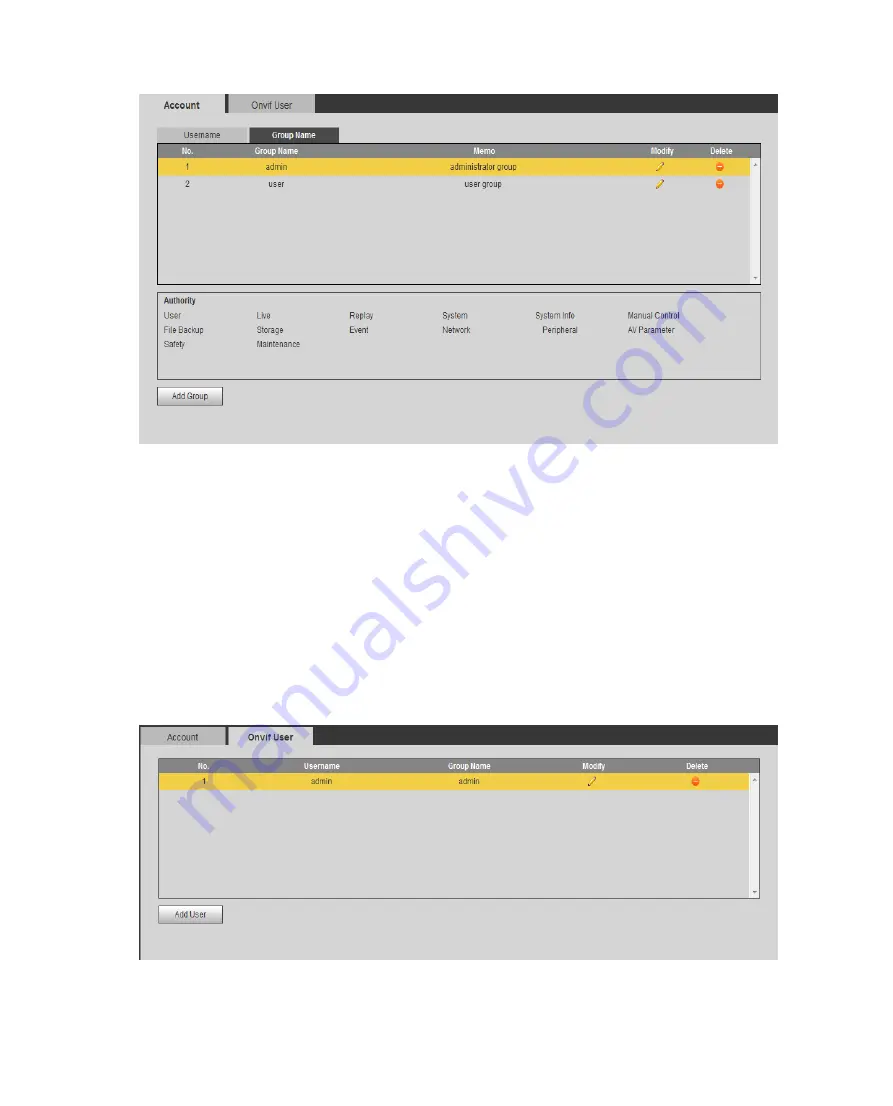
background image


Figure 6-95 Group 


Add group: Add user within group and set group right.  


Note:  


You cannot delete admin and user groups.  


You cannot delete group which contains currently logged in user.  


6.5.6.2.4  ONVIF User 

ONVIF user is separated from device user, so could be managed alone, see 

Figure 6-96


Rule same as i

Username

. 


Figure 6-96 

Summary of Contents for ITC231-RF1A-IR

Page 1: ...Dahua Intelligent Traffic HD Camera User s Manual For ITC231 RF1A IR Version 1 0 0 ZHEJIANG DAHUA VISION TECHNOLOGY CO LTD ...

Page 2: ... of outsiders being able to guess which ports you are using 3 Enable HTTPS SSL Set up an SSL Certificate to enable HTTPS This will encrypt all communication between your devices and recorder 4 Enable IP Filter Enabling your IP filter will prevent everyone except those with specified IP addresses from accessing the system 5 Change ONVIF Password On older IP Camera firmware the ONVIF password does n...

Page 3: ...ss Disabling UPnP is recommended when the function is not used in real applications 11 SNMP Disable SNMP if you are not using it If you are using SNMP you should do so only temporarily for tracing and testing purposes only 12 Multicast Multicast is used to share video streams between two recorders Currently there are no known issues involving Multicast but if you are not using this feature deactiv...

Page 4: ...t avoided could result in slight or moderate injury Indicates a potential risk which if not avoided may result in property damage data loss lower performance or unpredictable result Indicates dangerous high voltage Take care to avoid coming into contact with electricity Indicates a laser radiation hazard Take care to avoid exposure to a laser beam Electrostatic Sensitive Devices Indicates a device...

Page 5: ...ight be deviation between the actual value of some data and the value provided if there is any doubt or dispute please refer to our final explanation Please contact the supplier or customer service if there is any problem occurred when using the device We are not liable for any loss caused by the operations that do not comply with the Manual All trademarks registered trademarks and the company nam...

Page 6: ...the examination and repair work should be done by the qualified service engineers We are not liable for any problems caused by unauthorized modifications or attempted repair Environment The Device should be installed in a cool dry place away from conditions such as direct sunlight inflammable substances and explosive substances Accessories Be sure to use all the accessories recommended by manufact...

Page 7: ... 1 3 Remove Lens 7 3 2 TF card Installation 7 3 2 1 Installation 7 3 2 2 Remove TF card 8 3 3 I O Port 9 3 3 1 Install Cable 9 3 3 2 Remove Cable 9 4 System Network 10 5 Quick Configuration Tool 12 5 1 Change IP Address 12 5 2 Upgrade Device 13 5 3 Login WEB 15 5 4 Search Setting 16 6 Web Operation 17 6 1 Intro to WEB 17 6 1 1 First Time Login 17 6 1 2 Non First Time Login 19 6 1 3 Function 19 6 2...

Page 8: ...3 4 Lane Property 28 6 3 5 Complete 29 6 4 Query 29 6 4 1 Picture Query 29 6 4 2 Flow Query 32 6 4 3 Record Query 33 6 5 Configure 35 6 5 1 ITC 35 6 5 2 Camera 57 6 5 3 Network 66 6 5 4 Event 78 6 5 5 Storage 85 6 5 6 System 90 6 5 7 Information 99 6 6 Alarm 102 6 7 Logout 103 7 FAQ 104 ...

Page 9: ...ver photo Recognition Support plate vehicle color recognition function Support retrogradation over speed unfastened seat belt detection User Management Different user rights for each group and you may modify the setup anytime Search of online user Log Management Support 1024 log Support account right setup Storage According to user needs by WEB recording mode video files on the client computer res...

Page 10: ...otocol and interface can be set freely Support external NO light which can be triggered Power Supplying Support DC 12V input White Balance Auto white balance refers to the camera to restore the white object color It allows the camera to adjust the color temperature in indoor and outdoor environment Partial white balance refer to environment adjust target color Auto Exposure System can automaticall...

Page 11: ...t flashes when system is upgrading The red light flashes in safety mode F1 F1 F2 F2 AO1 AO2 3 ch output interface Switch may set output flashlight signal and strobe light signal Warning Page config must match actual light otherwise the light could be damaged IN1 IN2 IO input interface Provide 4 IO trigger snapshot interfaces or 4 alarm input interfaces A1 RS485 interface RS485_A1 interface this de...

Page 12: ...nc external signal source select external sync option it take effective immediately voltage range12 Vp p 36 Vp p or AC 12V AC 24V GPS External GPS antenna 1 USB interface Used to expand 3G 4G and Wi Fi 1 network interface Connect to standard Ethernet AUDIO IN OUT Autio input output Audio input output interface ABF Auto focus Auto focus RESET Reset Restore default settings Under normal work status ...

Page 13: ...Chart 2 1 2 2 Side Panel Figure 2 2 2 3 Front Panel Figure 2 3 ...

Page 14: ...3 Installation Warning To ensure the device is normally grounded and improve device reliability please connect port of device to the ground Figure 3 1 3 1 Install Lens Figure 3 2 ...

Page 15: ...screw next to focusing ring aim the lens at the mounting position of the lens on the camera rotate the lens clockwise until it is securely in place Step 3 Counterclockwise rotate the focusing ring until it is out for several mm and manually focusing Step 4 Use cross screwdriver to fasten screw fixing focusing ring 3 1 3 Remove Lens Figure 3 3 Step 1 Unplug the auto lens cable socket from the auto ...

Page 16: ...Figure 3 4 Install the TF card into the camera according to the proper installation position 3 2 2 Remove TF card Figure 3 5 Follow the TF card direction to remove the TF card from the device ...

Page 17: ... the corresponding button of cable groove Step 2 Insert the cable into the groove Step 3 Release the screwdriver 3 3 2 Remove Cable Step 1 Use the small slotted screwdriver to press the corresponding button of cable groove Step 2 Remove the cable out of the groove Step 3 Release the screwdriver ...

Page 18: ...4 System Network Please refer to Figure 4 1 Figure 4 1 Figure 4 2 ...

Page 19: ......

Page 20: ...l makes ConfigTool 4 09 0 as an example Please be aware that different versions may have different operation interfaces Double click the DH_ConfigTool exe icon you can see an interface is shown as in Figure 5 1 In the device list interface you can view device IP address port number subnet mask default gateway MAC address and etc Figure 5 1 5 1 Change IP Address Step 1 Open Quick Config Tool Step 2...

Page 21: ...vice to change its IP and click Modify IP Step 4 Set mode IP subnet mask and gateway Note When you modify IP select Same IP as to set all IPs to the same one Figure 5 2 Step 5 Click OK 5 2 Upgrade Device It supports single or batch upgrade device Step 1 Open Quick Config Tool Step 2 Click see Figure 5 3 ...

Page 22: ...Figure 5 3 Step 3 Select device to upgrade Single click Browse of device you want to upgrade Batch select device you want to upgrade and click Batch Upgrade Step 4 Select upgrade file see Figure 5 4 ...

Page 23: ... system shows progress Batch click OK so system starts to upgrade Note During upgrading as long as ConfigTool stays in upgrade interface when device connects again the upgrading will continue 5 3 Login WEB Click in device row to login WEB page See Figure 5 5 ...

Page 24: ...igure 5 5 5 4 Search Setting Click search device Figure 5 6 Current Segment Search select it search device in the same segment with PC Other segment search select it search device by start IP and end IP ...

Page 25: ...n the same segment Network segment is 192 168 1 X but do not set to 192 168 1 108 3 Ping device IP address command on PC check network Step 2 Set separate IP address subnet mask and gateway for host and device Step 1 If there is no router device in the network please allocate IP address in the same segment Step 2 If there is router device then please set corresponding gateway and subnet mask Step ...

Page 26: ...word and click Next you can enter WEB homepage Note If this is the first time you log in WEB please install plug in following instructions Before you installing plug in please go to Internet Options Security and enter active related plug in or enable prompt Figure 6 3 Note When you leave no operation on WEB for a long time you will see failed authentication box and must log in again ...

Page 27: ...n When you enter wrong username of password you can see Figure 6 5 If you have enter wrong username or password for 5 consecutive times the account will be locked for 5 minutes See Figure 6 6 Figure 6 5 Figure 6 6 6 1 3 Function Here uses DHI ITC231 RF1A IR as example Function Note Guide Guide user to quickly understand usage of WEB ...

Page 28: ...lient logout Chart 6 1 6 2 Live After you successfully log in WEB system shows Live interface here you can preview video picture and snapshot record Figure 6 7 6 2 1 Video Bit Stream Bar The video bit stream bar interface is shown as in Figure 6 8 Video Bit Stream Bar Figure 6 8 Video Bit Stream Bar Please refer to the following sheet for detailed information Parameter Function Main stream You can...

Page 29: ...t fit Window switch to large window and display adjusting window Control lens avaiable for motorized focus Full screen display 6 2 3 Common Function Bar The common function bar interface is shown as in Figure 6 10 Common Function Bar Figure 6 10 Common Function Bar Please refer to the following sheet for detailed information Icon Parameter Function Receive Pictures Check it to automatically receiv...

Page 30: ...o Setting Storage Destination Path AUZ Focus Click it you can preview AP Peak and AF Max parameters The closer the AF Peak value and AF Max are the better the focus effect will be Definition of the two parameters AF Peak this value is shown during live focus as video feature AF Max this value is best representation of video clarity Chart 6 3 6 2 4 Monitor Window Switch The monitor window switch in...

Page 31: ...eck vehicle plate pixel and confirm pixel of snapshot plate Figure 6 13 Step 1 Click snapshot to snapshot picture when the vehicle plate run into the green area detection area Step 2 Moving the small rectangle box to cover the area of plate ...

Page 32: ...etween the inner edge and outer edge of rectangle if size no matching the pixel of plate must be not easy for recognize please change the lens or the angle of camera Figure 6 14 6 3 2 Trigger Mode Before you set trigger mode select whether to use radar speed measurement see Figure 6 15 ...

Page 33: ...w is up Region Set area to be detected Area is shown in green box Lane Line According to actual traffic condition draw lane to be detected Each lane needs two lines Lane arrow means direction of vehicle Lane line is shown in blue with arrow Detect Line Draw intelligent border line for snapshot which is used as loop in actual traffic When a vehicle reaches this line it will snapshot Delete line is ...

Page 34: ... Line Click of corresponding lane to set Click to delete current lane line After setup is complete click OK to take effect Figure 6 16 Parameter Note Virtual Lane Set drawn virtual lane name Physical Lane According to actual condition set lane no Left Lane Line Set lane line type you can select white solid lane white void line and yellow lien Right Lane Line Chart 6 5 Step 4 Click OK below to take...

Page 35: ...ork brightness value Light Brightness Set light brightness LightArrMask Set light no Note valid in auto work mode only Auto Mode You can auto turn on off light according to time or brightness Time Set NO light on period 7 independent days in a week and 6 periods each day Brightness current brightness is below preset value light ON higher than preset value light OFF Note valid in auto work mode onl...

Page 36: ...lect device snapshot lane Left Lane Line Type Default is Solid White Line Right Lane Line Type Default is Solid White Line Event Config Note Different lane types correspond to different event types ANPR Select whether to snapshot ANPR vehicle Retrograde Select whether to snapshot retrogradation vehicle Illegal Parking Select to snapshot vehicle parked in authorized area Jam Select whether to snaps...

Page 37: ...own as in Figure 6 20 Picture Query Please select start time end time and event type Then please click search button you can see the corresponding files in the list Select the file s you want to download and then click download button system pops up a dialogue box then you can specify file name and path to download the file s to your local pc Click Ok to complete the download procedure ...

Page 38: ... it searches picture by logo Note ANPR mode only Lane Select device snapshot lane Speed range Search by speed range Plate Search by plate Record Interval Use this as filter to search picture Click this button to download link record Note After you enable link record violation picture will always has this icon linked record subject to actual condition Chart 6 8 Step 1 Enter search picture parameter...

Page 39: ... Download Picture Naming Download Create time image downloaded to a PC the modification time image attributes using a PC time Snap time image downloaded to a PC the modification time image attributes using a device snapping time Download Mode Select File Select the desired image which can be a radio or select multiple pictures which is to support batch download click download the Save dialog box w...

Page 40: ... picture and click Open to preview the image Figure 6 22 Search Local Picture Step 1 Click Open Local and select folder of picture Step 2 Select picture click Water Verify and you can see result in picture list Step 3 Select picture click Open or double click picture to preview picture 6 4 2 Flow Query Count vehicle flow in selected area Select Query Flow Query see Figure 6 23 ...

Page 41: ... time and end time for search Step 2 Click Search click Backup to back up to local PC Click Clear to view result 6 4 3 Record Query 6 4 3 1 Record Click record query you can see an interface is shown as in Figure 6 24 Record Query ...

Page 42: ...ttings enabled set the corresponding watermark character the default watermarks characters DigitalCCTV Select the video file click the Watermark check the system displays the checksum progress normal watermark See Figure 6 25 Watermark Step 1 Click Open Record select record file Step 2 Click Water Verify system shows progress and normal water mark info ...

Page 43: ...pletion the page shows watermark is finished 6 5 Configure 6 5 1 ITC 6 5 1 1 Lane Property User shall set related parameter according to their need ANPR device need different config of event Select Setting ITC Lane Property see Figure 6 26 ...

Page 44: ... enable The no corresponds to actual lane no Related Record Check the related record the time will be illegal to capture video set the length of recording time as shown in figure Working road Select road type Roadway Code Fill in according to actual condition Route Code Fill in according to actual condition Lane Select lane to snapshot ...

Page 45: ...hot ANPR vehicle Retrograde Choose whether to capture retrograde vehicles Illegal Parking Choose whether to capture stops at traffic ban driveway or sidewalk parking spaces finest vehicles Jam Snapshot traffic jam or not Pedestrian Snapshot pedestrian or not Chart 6 10 Click and see Advance Config in Illegal Type Config and you can see Advance Config interface Different events correspond to differ...

Page 46: ...l in violation name Illegal Code Set corresponding code of violation type Record Total Time s Set total record time of violation snapshot Time range is 5s 20s Record Pre Time s Set snapshot prerecord time length Time range is 0s 5s Note Total time of record is 3s longer than pre record time before snapshot Time Settings Set enabled time of snapshot 7 independent days in a week 6 periods each day C...

Page 47: ...ect week day or click Setting Step 2 Select period no to enable and manually enter start time Step 3 Click Yes 6 5 1 2 Snapshot Set max speed match method and location mode of snapshot The snapshot interface is shown as in Figure 6 29 Snapshot ...

Page 48: ...speed range Snap Position Mode Set camera snapshot location either fixed or auto mode Chart 6 12 6 5 1 3 Intelligent ANPR mode supports analysis of scene config speed measure config recognition config and advance config 6 5 1 3 1 Video Analysis Scene Setup Draw area line lane line and detection time in s scene and set Step 1 Select Setting ITC Intelligent Video Analyse Scene Setup See Figure 6 30 ...

Page 49: ...nformation Parameter Function Direction Means direction of moving in two algorithm Select Vehicle Head lane line downward Select Vehicle Rear lane line upward Region Set detect region Select and click on redraw to drawn region as green box in Figure 4 8 Lane line Draw lane according to actual condition Each lane requires two lines Arrow of lane represents moving direction Select and click on redra...

Page 50: ...l length Click Redraw to delete original line Chart 6 13 Step 4 After lane line is drawn it auto shows lane info Click corresponding lane to set Click to delete current lane line Click Yes you are done Figure 6 31 Parameter Note Virtual Lane Set drawn virtual lane name Physical Lane According to actual condition set lane no Left Lane Line Set lane line type you can select white solid lane white vo...

Page 51: ...ance from lower border to L pole Distance camera scene middle L2 Distance from middle line to L pole Chart 6 15 6 5 1 3 3 Video Analysis Recognition By setting recognition set snapshot of non plate vehicle recognition of plate vehicle location Select Setting ITC Intelligent Video Analyse Recognition see Figure 6 33 Recognition After setup is complete click OK Note Different models of product and w...

Page 52: ...cognize if driver wear seat belt Plate Unit Pixel Set min width max width min height and max height of plate Only min width and max width are valid Non motor category Select this argument capture non motorized vehicles and pedestrians Sensitivity Set to detect device sensitivity Analyse Select plate mode Head mode tail mode head prior mode and tail prior mode Chart 6 16 6 5 1 3 4 Video Analysis Ad...

Page 53: ...rameter information Parameter Note Advanced Options You can enter a custom algorithm expression implement special features custom Chart 6 17 6 5 1 4 OSD Config 6 5 1 4 1 Video OSD Set video channel OSD See Figure 6 35 Video OSD Step 1 Select Setting ITC OSD Config Video OSD ...

Page 54: ...itle and position a Click GPS Title b Select Turn on c Use the mouse to drag the yellow box or change the regional point coordinates select the time the title of the position Set flow info a Click Flow Info b Select Turn on d Sele Use the mouse to drag the yellow box or change the regional point coordinates set flow info position You can click to add customized region define OSD info The system su...

Page 55: ...icture title and each title has OSD option Note Select one picture title right click you can delete the picture caption Step 3 Select OSD black border position including up down and none Step 4 Set OSD info font and font plan You can set OSD font color below Step 5 Click More a box pops up see Figure 6 37 You can select auto change and set OSD isolator Select Customized and you can enter other iso...

Page 56: ...formation state by turns you can delete any OSD options Remove All Clear all selected OSD information New Line OSD information will be displayed on the picture branches Step 7 Click OK 6 5 1 5 Snap Cutout 6 5 1 5 1 Snap Cutout Check the snap cutout enable and click OK the system will recognize the license plate the main driver face copilot face image cutout a picture stored in the storage path Not...

Page 57: ...tra device interface is shown as in Figure 6 39 Extra Device Here you can view aux device type no and status Figure 6 39 Extra Device 6 5 1 6 2 Light 485 Config Set steady lamp frequency lamp work mode via 485 Select Setting ITC Extra Device Light 9485 Config ...

Page 58: ...or OFF Check Status Select to check status of light Light Brightness Set NO light normal working brightness Light ArrMask Set light no Note Auto work mode only Auto Mode According to time or brightness auto turn on off light Time Set NO period independent config 7 days a week with 6 periods per day Brightness When current brightness is below preset value enable NO light When current brightness is ...

Page 59: ...When checked set the number of matching characters and the minimum matching digits The system will match the license plate as the white list vehicle without matching each character with the license plate number which already exists in the white list data Card Word The checked characters are matched and unselected characters will not be analyzed Min Word When the number of matched characters meets ...

Page 60: ...ata see Chart 6 20 Start Time End Time Master of Car Plate Color Plate Number Plate Type Vehicle Color Vehicle Size 2015 3 12 0 00 2015 9 12 23 59 A 1 A11111 1 A 1 2015 9 12 0 00 2016 3 12 23 59 B 2 A22222 2 E 2 2016 3 12 0 00 2016 3 13 23 59 C 3 A33333 3 G 2 Chart 6 20 Note Plate color plate type vehicle color and vehicle size info is entered via code above corresponding to dropdown list ...

Page 61: ...st Once exceeding this period the plate will no longer be in white list Step 4 Enter vehicle owner name select whether to authorize barrier right Step 5 Check Continue Adding click OK Or uncheck Continue Adding click OK Batch import white list Steps Step 1 Progressively import white list add the first while data on WEB Step 2 Click Export and in pop up box click Save select path Click Save ...

Page 62: ...ath and click save 6 5 1 7 3 Black List Data Select Setup ITC BW List Black List Search Search whether a plate of vehicle exits in black list View vehicle details Import Export black list vehicle info Figure 6 44 For blacklist search import export and white list please see Figure 6 43 6 5 1 8 Traffic Flow 6 5 1 8 1 Traffic Flow Set lane and other statistical period Step 1 Select Setting ITC Traffi...

Page 63: ...Figure 6 45 Step 2 Set period Step 3 Set flow lane Step 4 Select Enable Step 5 Click OK 6 5 1 8 2 Flow Data Select Setting ITC Traffic Flow Flow Data see Figure 6 46 Figure 6 46 ...

Page 64: ...ent flow data to local 6 5 1 9 Device Direction 6 5 1 9 1 Device Direction Select Setting ITC Device Direction Device Direction see Figure 6 47 It shows info gotten from GPS or BeiDou system Figure 6 47 6 5 1 9 2 Device Attitude Select Setting ITC Device Direction Device Attitude enter Device Attitude interface See Figure 6 48 ...

Page 65: ... Click on default to restore default settings Figure 6 49 Intelligence Default 6 5 2 Camera 6 5 2 1 Attribute 6 5 2 1 1 General The general interface is shown as in Figure 6 50 General Here you can set camera parameters For different models you shall refer to its parameter Setup in this interface comes effective immediately ...

Page 66: ... When contrast is insufficient you may adjust this value Recommended value is 40 60 within 0 100 range Hue The value adjusts hue of image Default value is 50 It will not affect image brightness It has a relatively fixed value according to the sensor Recommended value is 40 60 within 0 100 range Saturation The value adjusts saturation of image Default value is 50 The higher the value the deeper the...

Page 67: ...utter interface is shown as in Figure 6 51 Shutter Select Setting Camera Attributes Shutter Figure 6 51 Shutter Please refer to the following sheet for log parameter information Parameter Function Shutter mode Support single shutter picture exposure mode scene mode gain mode can be separately set Video Tridim Denoise Select ON to enable 3D NR Scene Switch to other scenes to change sharpness ...

Page 68: ...r Temp Sharpness Set sharpness of each scene The higher the value the higher the contrast of detail will be and the image is clearer But when this value is too high image will have higher noise WDR Set WDR of each scene Lower brightness in highly bright area and improve brightness in relatively dark area so images in these areas can both be clear The higher the value the higher the WDR will be Gai...

Page 69: ...s in Figure 6 53 Metering Zone Select Setting Camera Attributes Metering Zone Figure 6 53 Metering Zone Please refer to the following sheet for log parameter information Parameter Function Metering zone Spot measure For moving vehicle Full measure For entire zone Partial measure For sensitive zone If the zone is bright entire zone will be dark and vice versa Backlight Front light According to actu...

Page 70: ...e 6 54 Figure 6 54 Step 2 Drag the bar to see speed size Step 3 Click dropdown list below Speed set ABF speed The higher the value the faster the speed will be Step 4 Click Auto Focus to auto set focus within monitoring video 6 5 2 2 Video 6 5 2 2 1 Video The video interface is shown as in Figure 6 55 Video Setting Camera Video Video ...

Page 71: ...and VBR Under VBR you can set image quality Bit rate Under VBR this value serves as upper limit Under CBR this value is fixed I frame interval It is the P frame between two I frame with range1 150 Default is two times frame rate Watermark settings By verifying watermark character you may check if record is edited Check front box to enable function Default watermark character is DigitalCCTV Only nu...

Page 72: ... set quality Quality Under VBR you can set quality 6 levels available Bit Rate In the fixed stream mode which is the upper limit value stream stream Under dynamic images if necessary by reducing the frame rate and image quality will be to ensure that the stream does not exceed the value In VBR mode this value has no meaning Refer to stream reference value the value stream to provide the best refer...

Page 73: ...ivacy masking and relay activation Note This device does not support this function Pic size Be consistent with main stream resolution Note This device does not support this function Quality Select snap quality from 6 levels Picture coding size KB Set picture coding size Note Please select either quality or picture coding size 6 5 2 2 3 Interest Area The interest area interface is shown as in Figur...

Page 74: ...ove All Click it to delete all set area Delete Click it delete the most recent interest area You can keep clicking it Or you can right click in any position of video to delete the interest area Chart 6 23 6 5 3 Network 6 5 3 1 TCP IP The TCP IP interface is shown as in Figure 6 58 TCP IP Select Setting Network TCP IP Warning Some models support dual Ethernet ports please DO NOT set them to the sam...

Page 75: ... W you can use wireless Ehternet card and edit card You must reboot device if you have set default card Currently it only supports wired Mode You can select from static and DHCP mode In DHCP mode it automatically search IP while you cannot set IP subnet mask gateway Plus IP subnet mask gateway display values from DHCP In static mode you shall manually set IP subnet mask gateway To switch from DHCP...

Page 76: ...6 5 3 2 Connection 6 5 3 2 1 Connection Set port parameters Parameter Note Max Connection Max connection 1 10 TCP Port Set TCP port 1025 65535 UDP Port Set UDP port 1025 65535 HTTP Port Set HTTP port HTTPs Port Set HTTPs port Chart 6 25 6 5 3 2 2 ONVIF User ONVIF is Open Network Video Interface Forum an online video to achieve a framework agreement which are produced by different vendors of networ...

Page 77: ...access device preview and monitor via server Select Setting Network Auto Register see Figure 6 60 Figure 6 60 Parameter Note Enable Select and enable auto register IP Address Need to register to server IP address Port Server used to auto register port no Sub Device ID Auto register device ID allocated by server For config must ensure auto connection to device SN Chart 6 26 6 5 3 4 HTTPS ...

Page 78: ... can make PC pass HTTPS by creating certificate or upload signed certificate Create Customized Certificate and Install Step 1 Select Setting Network HTTPS See Figure 6 61 Figure 6 61 Step 2 Create certificate Step 1 Click Create see ...

Page 79: ...ge Organization Organization of certificate usage Organization Unit Organization name of certificate usage Email Personal email or unit email of certificate usage Chart 6 27 Step 3 Click Create After you create certificate you can see the request in created request area Step 3 Click Install Note Click Delete in Certificate Installed area to delete installed certificate Step 4 Click Download to dow...

Page 80: ...Step 1 Double click see Figure 6 63 Figure 6 63 Step 2 Click Install Certificate See Figure 6 64 ...

Page 81: ...Figure 6 64 Step 3 Click Next see Figure 6 65 Figure 6 65 ...

Page 82: ...p Security Warning box click Yes Then Click OK Import is complete Step 6 Click OK Instalaltion is complete Device starts to reboot After reboot complete in Internet Explorer enter http device IP to access the device Install Signed Certificate After it gets signed certificate and key from digital signature organization it can import signed certificate and certificate key Step 1 Select Setting Netwo...

Page 83: ...y file of signed certificate Step 3 Click Upload The system starts to install certificate and after complete it generate property of the certificate in installation area Note Click Delete in Certificate Installed area to delete the installed certificate Step 4 Click Download to save root certificate Step 5 Install root certificate 1 Double click See Figure 6 68 ...

Page 84: ...Figure 6 68 2 Click Install Certificate See Figure 6 69 ...

Page 85: ...Figure 6 69 3 Click Next see Figure 6 70 Figure 6 70 ...

Page 86: ...In pop up Security Warning box click OK And click OK again 6 Click OK Step 6 Select Enable HTTPs click OK Device starts to reboot After reboot complete in Internet Explorer enter http device IP to access the device 6 5 4 Event 6 5 4 1 Alarm 6 5 4 1 1 Relay activation The relay activation interface is shown as in Figure 6 72 Relay Activation Step 1 Select Setting Event Alarm Relay Activation ...

Page 87: ...in Support 2 channels of alarm input Period Set alarm arm and disarm period Click on setup button to open period menu Anti dither During anti dither period only one alarm will be recorded Unit is second with range 0s 100 s Sensor type May set NO or NC Chart 6 28 Step 4 Select Relay out accordingly and set port no and alarm delay time Step 5 Click OK 6 5 4 1 2 Relay out ...

Page 88: ...tep 2 Click 1 2 or 3 Set 1 channel of alarm output Step 3 Click trigger to output alarm signal Step 4 Click Refresh to search alarm output status 6 5 4 2 Abnormity When the device has abnormality the system will trigger alarm Select Setting Event Abnormality select abnormity tab see figure shown below Figure 6 74 No Storage Card ...

Page 89: ...Figure 6 75 Capacity Warning Figure 6 76 Storage Error Figure 6 77 Disconnection Figure 6 78 IP Conflict ...

Page 90: ...ion Relay out When alarm occurs set corresponding relay out You must enable this function first Output Time Alarm will continue for X seconds after motion detect ends You can set X within 10 s 300 s Login Error Set allowance of login error range is 3 10 Rollover Angle Threshold Set rollover angle threshold unit is degree Pitch Angle Threshold Set pitch angle threshold unit is degree ...

Page 91: ...ne it will trigger alarm Step 1 Select Setting Event IVS Event Pedestrian See Figure 6 81 Figure 6 81 Step 2 Set parameters Parameter Note Lane Select lane no of detection zone Snapshot Select to enable snapshot Chart 6 30 Step 3 Click OK 6 5 4 3 2 Parking When detection zone has parking event it will trigger alarm Step 1 Select Setting Event IVS Event Parking see Figure 6 82 ...

Page 92: ...ote Lane Select lane no of detection zone Snapshot Select to enable snapshot Chart 6 31 Step 3 Click OK 6 5 4 3 3 Retrograde Select Event IVS Event Retrograde see Figure 6 83 Figure 6 83 6 5 4 3 4 Jam When traffic jam occurs it will trigger alarm See Figure 6 84 ...

Page 93: ...ct to enable snapshot Chart 6 32 6 5 5 Storage 6 5 5 1 Destination 6 5 5 1 1 Point Set storage of snapshot and record Snapshot event has local storage and FTP Record event has local storage Select Setting Storage Destination Point select storage method for snapshot and record See Figure 6 85 6 5 5 1 2 Local ...

Page 94: ... storage when disk is full Select Setting Storage Destination Local see Figure 6 86 Local Figure 6 86 Local 6 5 5 1 3 FTP FTP You must enable FTP before selecting it for current storage When disconnection occurs or malfunctions it saves file or snapshot to local TF card See Figure 6 87 FTP ...

Page 95: ...t FTP servers Enable Enable the FTP server storage point Server IP The IP address of the FTP server Encode Mode Picture naming for the Chinese character encoding there are two optional UTF 8 and GB2312 When you click Test two files that use UTF 8 and GB2312 encoding respectively are created on the FTP server to determine how the server is encoded Port FTP server port Username and Password FTP serv...

Page 96: ...pload by IP address or MAX address Max support two platforms Quickly add platform client Browse to view IP and MAC address of all online platform select one address and click OK to add See Figure 6 88 Client Figure 6 88 Client 6 5 5 1 5 Path Path Config record and snapshot includes local TF card storage and FTP storage You cannot select local and local emergency at the same time The path interface...

Page 97: ...l Select record mode and record stream If you select Off for record mode then you cannot link record See Figure 6 90 Record Control Select Setting Storage Record Control select Automatic or Manual record and select main stream or sub stream ...

Page 98: ...Note Record Mode select Automatic or Manual record or off Record Stream select main stream or sub stream Chart 6 34 6 5 6 System 6 5 6 1 General 6 5 6 1 1 General The general interface is shown as in Figure 6 91 General Figure 6 91 General ...

Page 99: ...ing flag Language Select language and then close IE When you log in again system language will change Video standard Display device video standard such as PAL Machine Group Enter local device unit name Machine Address Enter snapshot location Chart 6 35 6 5 6 1 2 Date Time The date time interface is shown as in Figure 6 92 Date Time Figure 6 92 Date Time ...

Page 100: ...vice time zone Interval Set device update period 6 5 6 2 Account 6 5 6 2 1 Account Rule Note Account has two levels as group and username Group supports max of 8 and username supports max of 18 Default group includes admin and user Group name cannot be repeated Each user belongs to one group only You may add and delete group and set group User right within a group can be customized as long as with...

Page 101: ...right By default there are three users admin 888888 and 666666 Their passwords are the same as corresponding username Admin and 888888 are admin account by default while 666666 is user account which has monitor right only Enter add user interface input username and password and select its group Username shall not exceed right of its group We recommend you to set user right lower than admin right T...

Page 102: ...sword supports 0 15 characters including letter and number only Note You cannot modify right of the logged in account You cannot modify or delete admin 888888 and 666666 accounts Account who has right to modify other account can modify other user account besides its own You cannot delete currently logged in account 6 5 6 2 3 Group The group interface is shown as in Figure 6 95 Group Here you can a...

Page 103: ...roup right Note You cannot delete admin and user groups You cannot delete group which contains currently logged in user 6 5 6 2 4 ONVIF User ONVIF user is separated from device user so could be managed alone see Figure 6 96 Rule same as in Username Figure 6 96 ...

Page 104: ...s reliable SSD server is OFF by default you can select SSH Enable to enable it See Figure 6 98 Figure 6 98 6 5 6 3 2 IP Filter You can add delete Trust List and Banned List in IP Filter interface Select Setting System Safety IP Filter see Figure 6 99 Click Default to restore default setting click OK to save ...

Page 105: ...igure 6 100 Default Note Network IP address account info and system log cannot be restored to default Each parameter of camera will be restored to default 6 5 6 5 Import Export The import export interface is shown as in Figure 6 101 Import Export Step 1 Select Setting System Import Export ...

Page 106: ...e is shown as in Figure 6 102 Auto Maintain Figure 6 102 Auto Maintain User can automatically reboot system and delete old files You shall set auto reboot schedule and set file time period for auto delete old file to delete file within certain time periods Click on save to make setup effective 6 5 6 7 Upgrade When system upgrades you shall select firmware file Firmware file ends in bin Please main...

Page 107: ...counters error during upgrading the device may malfunction 6 5 7 Information 6 5 7 1 Version The version interface is shown as in Figure 6 104 Version Select Setting Information Version to view current WEB version Note Different device version has different info subject to WEB Figure 6 104 Version ...

Page 108: ...ep 1 Select Setting Information Log Log Figure 6 105 Log Step 2 Enter start time end time and select type Step 3 Click Search you can stop search as you need Step 4 You can view search result and back up it Back up file will be stored at local in txt format 6 5 7 2 2 Remote Log Remote log allows the device to save key login into network log server which is an important clue Log server must be set ...

Page 109: ...rver IP address port device number Step 4 Click OK 6 5 7 3 Online User The online user interface is shown as in Figure 6 107 Online User Here displays online user and their group IP address and login time Figure 6 107 Online User 6 5 7 4 Work State Go to Setting Information Work State ...

Page 110: ...pe Parameter Note Alarm Type Storage Full When storage is full trigger alarm Storage Error When storage has error trigger alarm External Alarm Alarm input device alarm No Storage No storage and trigger alarm Black List Detect plate in blacklist trigger alarm Gyro Abnormal Attitude When device attitude has abnormity trigger alarm ...

Page 111: ...tect illegal access trigger alarm Operation Listen Alarm WEB subscribed alarm type selected above from device and device will notify WEB by alarm and WEB notify users Alarm Tome Play Alarm Tone Alarm has tone you can customize alarm sound Tone Path Customize alarm sound storage path Chart 6 36 6 7 Logout Click Logout to log out See Figure 6 110 Figure 6 110 ...

Page 112: ...rade operation failed You can use port 3800 to continue upgrade Recommended TF card brand Kingston 4GB Kingston 1GB Kingston 16GB Transcend 16GB SanDisk 1G SanDisk 4G Usually we recommend the 4GB or higher high speed card in case the slow speed results in data loss Web control webrec cab not pop up Please set IE security level to low and enable ActiveX plug in Warning This version of explorer supp...

Page 113: ...JIANG DAHUA VISION TECHNOLOGY CO LTD No 1199 Bin an Road Binjiang District Hangzhou P R China Postcode 310053 Tel 86 571 87688883 Fax 86 571 87688815 Email overseas dahuatech com Website www dahuatech com ...

Reviews: