background image


15

3


Quick Configuration Tool 

3.1


Overview  

Quick configuration tool can search current IP address, modify IP address. At the same time, you 
can use it to upgrade the device.  
Please note the tool only applies to the IP addresses in the same segment. 

3.2


Operation 

Double click the “ConfigTools.exe” icon; you can see an interface is shown as in Figure 3-1.  
In the device list interface, you can view device IP address, port number, subnet mask, default 
gateway, MAC address and etc.  


Figure 3-1 

Select one IP address and then right click mouse, you can see an interface is shown as in Figure 
3-2. 


Figure 3-2 

Summary of Contents for IPC-HF3200 Series

Page 1: ...Megapixel Indoor IPC Quick Start Guide Version 3 0 0...

Page 2: ...working temperature ranges from 10 to 60 Please keep it away from the electromagnetic radiation object and environment Please keep the sound ventilation Do not allow the water and other liquid falling...

Page 3: ...ii Accessory Name Amount IPC Unit 1 C CS adapter 1 Quick Start Guide 1 CD 1...

Page 4: ...ve Lens 8 2 2 SD Card 8 2 2 1 Installation 8 2 2 2 Remove 9 2 3 3G Card 9 2 3 1 Installation 9 2 3 2 Remove 10 2 4 3G WIFI Antenna 11 2 4 1 Installation 11 2 4 2 Remove 12 2 5 I O Port 12 2 5 1 Instal...

Page 5: ...iv Appendix Toxic or Hazardous Materials or Elements 21...

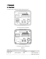
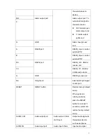
Page 6: ...elow See Figure 1 1 The rear panel with the network port The rear panel with the 100M fiber port Figure 1 1 Please refer to the following sheet for detail information Interface Name Connector Function...

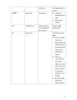
Page 7: ...tus green light is on z Display record status Record green light flashes STATUS Indication Light Yellow light z Detect the wireless device yellow light is on 3G Connect to 3G card Please note it is fo...

Page 8: ...2_RX RS232 receive end TX RS232 port RS232_TX RS232 COM send out end G GND RS232 ground end NA IR light port External IR light signal control port RESET RESET button Restore factory default setup When...

Page 9: ...P fiber module Transmit 100M Ethernet data SD SD card port Connect to SD card Note z When you install the SD card please make sure current card is not in write mode and then you can install it to the...

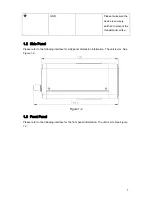
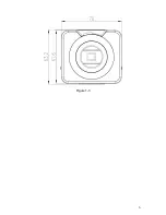
Page 10: ...hunderstorm strike 1 2 Side Panel Please refer to the following interface for side panel dimension information The unit is mm See Figure 1 2 Figure 1 2 1 3 Front Panel Please refer to the following in...

Page 11: ...6 Figure 1 3...

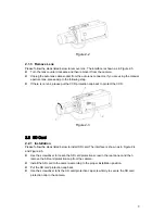
Page 12: ...ring and then turn counter clockwise to move the focusing ring out for several millimeters Now you can focus manually and check the video is clear or not If you can not see the clear video you can adj...

Page 13: ...D protection cap back to protect the CCD Figure 2 3 2 2 SD Card 2 2 1 Installation Please follow the steps listed below to install SD card The interface is shown as in Figure 2 4 and Figure 2 5 z Use...

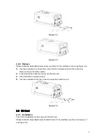
Page 14: ...rear panel Remove the cap from the camera z Follow the SD card direction to remove the SD card z Insert the SD card protection cap z Use the screwdriver to fix the screw to secure the protection cap F...

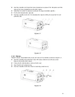
Page 15: ...ix the 3G card protection cap screw firmly to secure the 3G card protection cap Figure 2 7 Figure 2 8 2 3 2 Remove Please follow the steps listed below to remove 3G card The interface is shown as Figu...

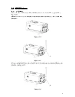
Page 16: ...read of the rear panel See Figure 2 10 Please turn according to the direction in the following figure until antenna is secure firmly See Figure 2 11 Figure 2 10 Figure 2 11 After you fix the 3G WIFI a...

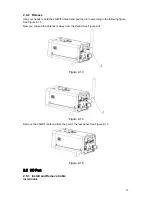
Page 17: ...ding to the following figure See Figure 2 13 Now you can see the antenna is away from the thread See Figure 2 14 Figure 2 13 Figure 2 14 Remove the 3G WIFI antenna from the port of the rear panel See...

Page 18: ...ollowing figure for alarm input information See Figure 2 17 Alarm input When the input signal is idle or grounded the device can collect the different statuses of the alarm input port When the input s...

Page 19: ...g figure for external IR light information See Figure 2 19 IR synchronization input signal When the external IR light is on the signal cable from the board outputs the 3 3V 1mA It outputs the 0V when...

Page 20: ...y applies to the IP addresses in the same segment 3 2 Operation Double click the ConfigTools exe icon you can see an interface is shown as in Figure 3 1 In the device list interface you can view devic...

Page 21: ...terface Or you can select an IP address and then click the Login button to go to the login interface See Figure 3 4 In Figure 3 4 you can view device IP address user name password and port Please modi...

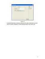
Page 22: ...17 Figure 3 5 For detailed information and operation instruction of the quick configuration tool please refer to the Quick Configuration Tool User s Manual included in the resources CD...

Page 23: ...y IPC default IP address is 192 168 1 108 Subnet mask is 255 255 255 0 Gateway is 192 168 1 1 z Use order ping IP camera address to check connection is OK or not 4 2 Login and Logout Open IE and input...

Page 24: ...se click OK button system can automatically install the control When system is upgrading it can overwrite the previous Web too If you can t download the ActiveX file please check whether you have inst...

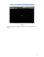
Page 25: ...20 Figure 4 4 Please refer to the Web Operation Manual included in the resource CD for detailed operation instruction...

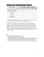
Page 26: ...friendly use period EFUP period the toxic or hazardous substance or elements contained in products will not leak or mutate so that the use of these substances or elements will not result in any sever...

Reviews: