background image


59 

Step 2  Set parameters. 

  Cover area: It is to set cover area section. Drag the mouse to set proper section size. 

In one channel video, system max supports 4 zones in one channel.   

  Preview/monitor: The cover area has two types. Preview and Monitor. Preview: You 

can view the mask zone on the the VGA displayer or the connected small screen, 

but you cannot view the mask zone on the record file or WEB. The Monitor item is 

checked at the same if you select Preview. Monitor: You cannot view the mask zone 

on the the VGA displayer or the connected small screen, but you can view the mask 

zone on the record file or WEB. 

  Time display/Channel display/License No./GPS display: Select a channel to overlay 

title  and  drag  the  title  to  the  corresponding  position.  The  overlay  function  can 

overlay title on the real-time monitor video or the playback file. Click time title and 

then  click  Monitor,  click  Set  button  to  drag  the  overlay  title  to  the  corresponding 

position. 

Step 3  Click Save button.   


4.3.1.2.3  Snapshot   

Please install HDD or set FTP. Refer to chapter 4.3.2.3 FTP to set FTP parameters.   

The snapshot includes regular snapshot and event snapshot. 

When these two modes are enabled at the same time, the event snapshot has higher priority than 

regular snapshot. If there is corresponding alarm, then the event snapshot is triggered. If there is 

no alarm, then regular snapshot is valid.   

Step 1  From Main menu->Setting->System->Encode, click Snapshot button.   

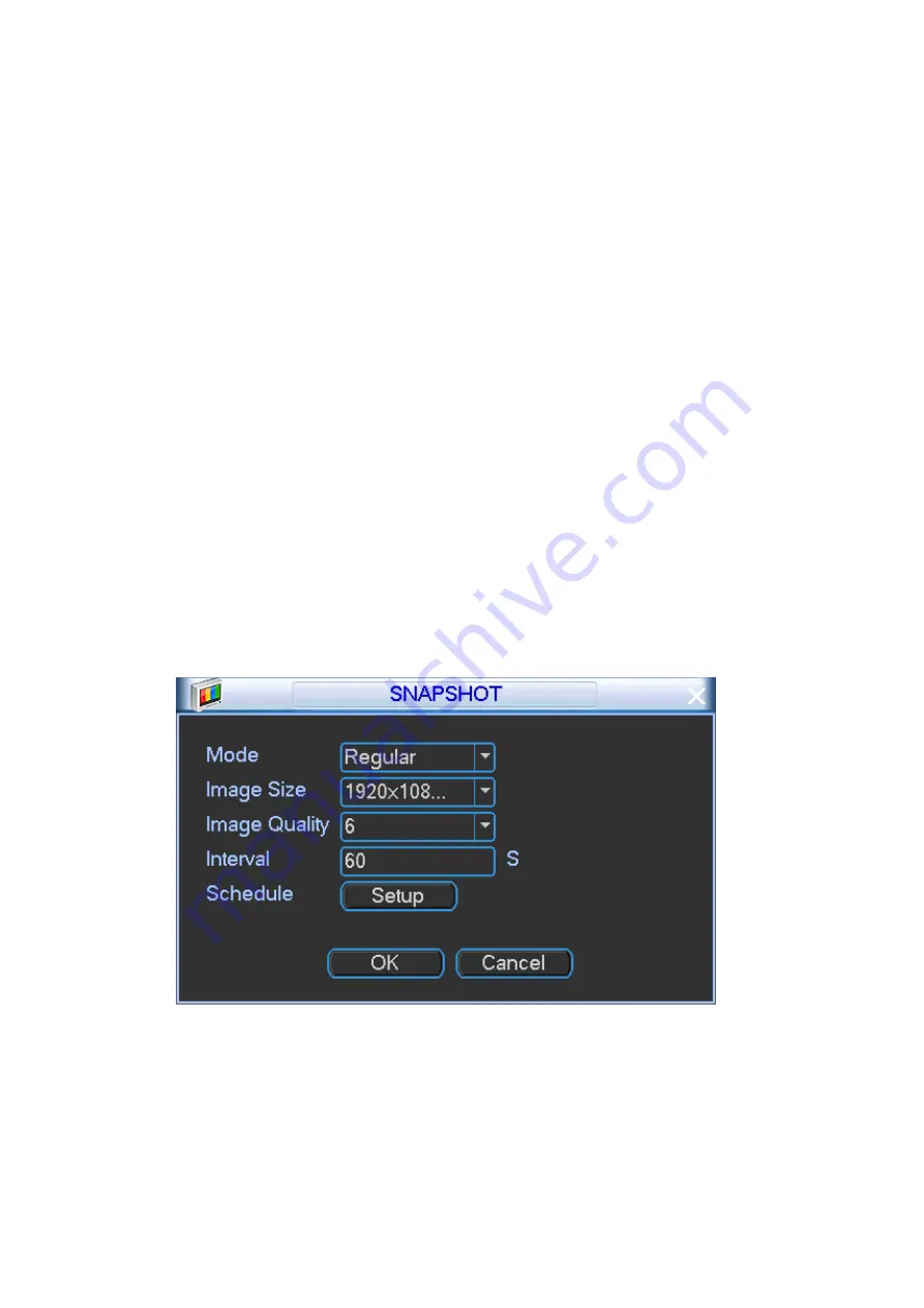
Enter Snapshot interface. See Figure 4-47.   


Figure 4-47 

Step 2  Set parameters.   

  Snapshot mode: There are two modes: regular and event. If you set regular mode, 

you  need  to  set  snapshot  interval.  If  you  set  event  snapshot,  you  need  to  set 

snapshot activation operation.   

  Image size: Please set according to the actual situation. 

  Image quality: Here you can set snapshot quality. The value ranges from 1 to 6. The 

Summary of Contents for HFD23

Page 1: ...HDCVI Mobile Digital Video Recorder User s Manual V 1 1 2 ...

Page 2: ...tput Connection 16 2 8 1 Alarm Input and Output Details 16 2 8 2 Alarm Input Port 17 2 8 3 Alarm Output Port 17 2 9 Remote Control 19 2 10 Mouse Operation 20 3 Boot up and Shut down 22 3 1 Boot up 22 3 2 Shut Down 22 4 Local Operation 23 4 1 Getting Started 23 4 1 1 Initialize Device 23 4 1 2 Login 25 4 1 3 IP Address and Port 27 4 1 4 General Information 29 4 1 5 Manual Record 31 4 1 6 Schedule 3...

Page 3: ...ime Monitor 117 5 5 2 PTZ 118 5 5 3 Image Relay out 119 5 5 4 Zero channel encoding 120 5 6 Setup 120 5 6 1 Camera 120 5 6 2 Network 125 5 6 3 Event 137 5 6 4 Storage 146 5 6 5 System 149 5 6 6 Vehicle 162 5 7 Information 163 5 7 1 Version 163 5 7 2 Log 163 5 7 3 Online User 164 5 7 4 Satellite 165 5 7 5 Network Sniffer 165 5 8 Playback 165 5 8 1 Playback Record 167 5 8 2 Clip and Save Record 167 ...

Page 4: ...me Thank you for purchasing our mobile network video recorder This user s manual is designed to be a reference tool for your system Contact your local retailer ASAP if something is missing or damaged in the bag ...

Page 5: ... authorized users are able to access the system 2 Change Default HTTP and TCP Ports Change default HTTP and TCP ports for systems These are the two ports used to communicate and to view video feeds remotely These ports can be changed to any set of numbers between 1025 65535 Avoiding the default ports reduces the risk of outsiders being able to guess which ports you are using 3 Enable HTTPS SSL Set...

Page 6: ...our router or modem Normally this would be a good thing However if your system automatically forwards the ports and you leave the credentials defaulted you may end up with unwanted visitors If you manually forwarded the HTTP and TCP ports in your router modem this feature should be turned off regardless Disabling UPnP is recommended when the function is not used in real applications 11 SNMP Disabl...

Page 7: ...the outside world and cannot be accessed directly 16 Isolate DVR and IP Camera Network The network your DVR and IP camera resides on should not be the same network as your public computer network This will prevent any visitors or unwanted guests from getting access to the same network the security system needs in order to function properly ...

Page 8: ... are designed to provide reasonable protection against harmful interference in a commercial environment Operation of this equipment in a residential area is likely to cause harmful interference in which case the user will be required to correct the interference at his own expense For class B device these limits are designed to provide reasonable protection against harmful interference in a residen...

Page 9: ... not liable for any problems caused by unauthorized modifications or attempted repair 5 Environment The DVR should be installed in a cool dry place away from direct sunlight inflammable explosive substances and etc This series product shall be transported storage and used in the specified environments 6 Accessories Be sure to use all the accessories recommended by manufacturer Before installation ...

Page 10: ...n risk Indicates presence of high power laser radiation Tips It is intended to help you to fix a problem or save your time Note Provides additional information to emphasize or supplement important points of the main text Revision History SN Version No Contents Release Date 1 V1 0 0 Initial release 2015 08 2 V1 1 0 Adjust chapters Optimize chapter contents Add device initialization and reset admin ...

Page 11: ... electronic version the electronic version shall prevail All the designs and software are subject to change without prior written notice The product updates might cause some differences between the actual product and the Manual Please contact the customer service for the latest program and supplementary documentation There still might be deviation in technical data functions and operations descrip...

Page 12: ... design It adopts general anti shock design such as mechanical anti shock measures electronic anti shock measures and patent software anti shock measures It integrates device anti shock and general anti shock mechanism together No fan design The traditional fan design has the noise easy to get dust water and has high power consumption No fan design is the tendency in current high end vehicle elect...

Page 13: ...ess function PTZ control Support PTZ control via netwrok Support various decode protocols to allow the PTZ to control the speed dome Intelligent operation Mouse operation Support short cut menu to copy paste for the same contents on the menu Satellite positioning The positioning information can activate the record function while the search function can activate the vehicle movement track Note This...

Page 14: ...screen Compression Standard Video Compression H 264 dual stream Audio Compression G711a PCM and G711u Video monitor Video Input 4 ch network compression video input Video Output 1 ch PAL NTSC aviation port 1 0VP P 75Ω composite video signal output Support 1 ch TV video output at the same time Support VGA video output Video Standard Support PAL NTSC Record Speed Real time Mode PAL 1f s to 25f s per...

Page 15: ...n one SATA port Support one 2 5 inch SATA HDD max 2TB and one SD card max 128GB Space Occupation Audio PCM 28 8Mbyte hour Video 56byte hour 5662Mbyte hour Record and playback Recording Mode Manual recording schedule recording and alarm recording Priority Manual recording alarm recording schedule recording Recording Length 1 to 120 minutes single record duration Default setup is 60 minutes Playback...

Page 16: ...ameter setup Support network signal status indication function Motion Detection and Alarm Video Loss Alarm can activate external alarm or screen message prompt Alarm responding time 5s Alarm Pre record Alarm can trigger pre record function Pre record time ranges from 5 to 30s External Alarm Support record activation function or activate external alarm or screen message in specified period Manual A...

Page 17: ...on No limit to the user or group amount Password security Password modification Administrator can modify other user s password Account lock strategy Five times login failure in thirty minutes may result in account lock Upgrade WEB client or update tool Login Logout and Shutdown Password login protection to guarantee safety User friendly interface when login Provide the following options Logout shu...

Page 18: ...the function keys in the front panel and the ports in the rear panel please refer to the appendix for detailed information The model in the front panel is very important please check according to your purchase order The label in the rear panel is very important too Usually we need you to represent the serial number when we provide the service after sales 2 3 Front Panel The front panel is shown as...

Page 19: ...dicator light The blue light is on when 3G function is normal Note Only the unit of 3G module supports this function 13 Wi Fi indicator light The blue light is on when Wi Fi function is normal Note Only the unit of Wi Fi function supports this function 14 Remote control receiver It is to receive the signal from the remote control 15 Door lock unlock Device on off button Please unlock the device be...

Page 20: ...of 3G 4G module supports this function 12 RJ45 network port Network port 2 13 Extension port Extension port Please refer to Figure 2 5 for detailed information 14 Alarm input output port Alarm input output port GND port and 12V output Please refer to chapter 0 for detailed information 15 RS485 and CAN BUS port RS485 communication port It can control PTZ Reserved port For data exchange between vehi...

Page 21: ...e 2 4 SN Function SN Function 1 Power input positive end 3 4 GND 2 Power input positive end 5 ACC input Extend Port The extend port is shown as in Figure 2 5 Figure 2 5 Please refer to the following sheet for detailed information SN Function SN Function 5 5V output Bottom line USB data 5 USB 5V Top line VO AV video output IR IR receiver port GND USB data RX RS232 RX ...

Page 22: ...ND Mic Out 2 5 SIM Card Installation Install SIM card to connect device to the internet Note This series product does not support Micro SIM or Nano SIM card Preparation Before the installation please shut down the device and unplug the power cable This series product supports built in SIM card See Figure 2 7 Step 1 Remove the HDD box Step 2 Push the SIM card slot to the back and open the SIM card ...

Page 23: ...ase purchase separately and follow the contents listed below to install WARNING Shut down the device and unplug the power cable before install remove the HDD The e lock on the right side of the front panel shall be unlocked when you install remove the HDD Please lock the button before you boot up the device Step 1 The HDD box and the parts are shown as below See Figure 2 8 It includes bottom board...

Page 24: ...ou can see an interface shown as in Figure 2 9 Figure 2 9 Step 3 Now you can see an interface shown as in Figure 2 10 Use four screws to secure the HDD on the bracket and then use two screws to fasten the bracket on the bottom board Step 4 Use screws to secure HDD box bottom The HDD installation is complete Figure 2 10 ...

Page 25: ...installed in a cool dry place away from direct sunlight inflammable explosive substances and etc The camera and the DVR should have the same grounding to ensure the normal operation of the camera Guarantee stability and reliability of the transmission line Please use high quality sound shielded BNC Please select suitable BNC model according to the transmission distance If the distance is too long ...

Page 26: ...place the monitor please pay attention to the following points Please use a VGA cable if you want to use VGA monitor Refer to chapter 2 4 Rear panel for VGA converter cable type information To defer aging do not allow the pc monitor to run for a long time Regular demagnetization will keep device maintain proper status Keep it away from strong electromagnetic interference devices Using TV as video ...

Page 27: ...y result in relay damage Please use the co contactor to realize the connection between the alarm output port and the load PTZ connection Ensure the decoder has the same grounding with DVR otherwise you may not control the PTZ Shielded twisted wire is recommended and the shielded layer is used to connect to the grounding Avoid high voltage Ensure proper wiring and some thunder protection measures F...

Page 28: ...COM end and COM end of the alarm detector Provide external power to the alarm detector Please parallel connect the Ground of the DVR and the ground of the alarm detector Please connect the NC port of the alarm sensor to the DVR alarm input ALARM Use the same ground with that of DVR if you use external power to the alarm device Figure 2 14 2 8 3 Alarm Output Port Alarm output is on off signal alarm...

Page 29: ...meter Insulation resistance 1000MΩ 500VDC Media pressure Between loop and contract 1000VAC 1min Between separated contact 400VAC 1min Operation time Rated voltage 5ms Release time Rated voltage 5ms Bound time Rated voltage About 5ms Loop temperature rise Rated voltage 65K Strike 98m s2 Vibration 10Hz 55 Hz 3 3mm Double amplitude Humidity 98 RH 40 Temperature 30 70 Weight About 2 2g leading out end...

Page 30: ...ower button Click it to boot up or shut down the device 2 Address Click it to input device number so that you can control it 3 Forward Various forward speeds and normal speed playback 4 Slow play Multiple slow play speeds or normal playback 5 Next record In playback mode playback the next video 6 Previous record In playback mode playback the previous video 7 Play Pause In pause mode click this but...

Page 31: ...ce 11 Direction keys Switch current activated control go to left or right In playback mode click up down button to switch playback channel In 1 window playback mode click left right button to control playback speed Aux function such as switch the PTZ menu enable disable reuse button 12 Confirm menu key go to default button go to the menu 13 Multiple window switch Switch between multiple window and...

Page 32: ...s character In numeral input mode _ stands for clear and stands for deleting the previous numeral Double left click mouse Implement special control operation such as double click one item in the file list to playback the video In multiple window mode double left click one channel to view in full window Double left click current video again to go back to previous multiple window mode Right click mo...

Page 33: ...s the first time to boot up the device or you have restored factory default settings device goes to initialization interface after it booted up Please follow the prompts to initialize the device first Use ACC to boot up Turn the vehicle key to the ACC the power indicator light is on and device is booting up The device is in preview mode by default The record mode is auto Refer to chapter 4 1 5 Man...

Page 34: ...change the password regularly Please follow the steps listed below Step 1 Boot up DVR Device displays device initialization interface See Figure 4 1 Figure 4 1 Step 2 Set login password of admin User name The default user name is admin Password confirm password The password ranges from 8 to 32 digitals It can contain letters numbers and special characters excluding The password shall contain at le...

Page 35: ...ty system Step 3 Click Next device goes to the following interface See Figure 4 2 Figure 4 2 Step 4 Set unlock pattern After set unlock pattern device goes to password protection interrface See Figure 4 3 Note Device adopts unlock pattern to login by default if you have set pattern here If there is no unlock pattern please input the password to login Click Skip if there is no need to set unlock pa...

Page 36: ...input email here or you need to update the email information please go to the main menu Setting System Account Modify user to set Refer to chapter 4 3 6 2 Modify user for detailed information Security question Set security questions and corresponding answers Properly answer the questions to reset admin password In case you have not input security question here or you need to update the security qu...

Page 37: ...interface to login by default Click to view the prompt information to help you remember password In case you forgot password click to answer security questions or use the email to reset password Refer to chapter 4 3 6 7 Reset password for detailed information Step 2 The default user is admin and then input the corresponding password the password you set during initialization process Step 3 Click O...

Page 38: ...to mark a specified network MAC address Usually it includes an organization of multiple level Default gateway Here you can input the default gateway Please note system needs to check the validity of all IPv6 addresses The IP address and the default gateway shall be in the same IP section That is to say the specified length of the subnet prefix shall have the same string DHCP It is to auto search I...

Page 39: ...you can select the priority between fluency video qualities LAN download System can process the downloaded data first if you enable this function The download speed is 1 5X or 2 0X of the normal speed Important For the IP address of IPv6 version default gateway preferred DNS and alternate DNS the input value shall be 128 digit It shall not be left in blank Figure 4 6 Step 3 Network Service Optiona...

Page 40: ...ystem time Note Since system time is very important do not modify time casually unless there is a must Before your time modification please stop record operation first Date format There are three types YYYYY MM DD MM DD YYYYY or DD MM YYYY Date separator There are three denotations to separate date dot beeline and solidus DST Here you can set DST time and date Please enable DST function and then c...

Page 41: ...re you can set vehicle plate number Auto logout Here is for you to set auto logout interval once login user remains inactive for a specified time Value ranges from 0 to 60 minutes Preview bar Check the box here system displays the navigation bar on the interface when you boot up device the next time Otherwise it goes to the system login interface directly You can check the box to select overlay po...

Page 42: ...mouse or in the main menu Advanced Manual Record Enter Manual record interface See Figure 4 11 Step 2 Set parameters Manual The highest priority After manual setup all selected channels will begin ordinary recording Schedule Channel records as you have set in recording setup Main Menu Setting Schedule Stop Corresponding channel stop recording Enable disable Corresponding channel start stop regular...

Page 43: ...ecord the video before the event occurs into the file The value ranges from 0 to 30 seconds depending on the bit stream 0 means pre record function is null Redundancy System supports redundancy backup function It allows you backup recorded file in two disks You can highlight Redundancy button to activate this function Please note before enable this function please set at least one HDD as redundant...

Page 44: ...ogged in you can go to 4 window preview interface directly See Figure 4 13 Tips If you want to change position of channel 1 and channel 2 when you are previewing you can left click mouse in the channel 1 and then drag to channel 2 release mouse you can switch channel 1 and channel 2 positions ...

Page 45: ...r Device internal temperature Vehicle speed Device 3G 4G network connection status Refer to chapter 4 3 3 1 3G 4G for detailed information 3G 4G network connection failed 3G 4G network connection succeeded Device Wi Fi network connection status Refer to chapter 4 3 3 2 Wi Fi for detailed information Wi Fi network connection failed Wi Fi network connection succeeded ...

Page 46: ... 2 When motion detection alarm occurs system displays this icon 3 When video loss alarm occurs system displays this icon 4 2 1 2 Preview Control Move you mouse to the top center of the video of current channel you can see system pops up the preview control interface If your mouse stays in this area for more than 6 seconds and has no operation the control bar automatically hides See Figure 4 14 Fig...

Page 47: ...igure 4 15 Window Switch System supports 1 4 8 9 window You can select from the dropdown list See Figure 4 16 Figure 4 16 PTZ Control Before you go to PTZ control interface please go to chapter 4 2 2 to set PTZ parameter Click it to go to PTZ interface See Figure 4 17 ...

Page 48: ...hapter 4 1 5 Record control for detailed information Alarm Output It is to set alarm output mode Please refer to chapter 4 3 4 4 Alarm output Device Info Please refer to chapter 4 4 2 2 Device info for detailed information Zero channel encoding Click to go to zero channel encoding interface Please refer to chapter 4 2 1 4 3 Zero channel encoding for detailed information Main Menu Click to go to th...

Page 49: ...e Please note it supports 1 window tour mode only Note Tour priority Alarm tour motion detect tour general tour Zero Channel Encoding Multiple Preview It is to set encode mode resolution frame rate overlay information and etc Refer to chapter 4 2 1 4 2 Zero channel encoding for detailed information Video mirror Set channel left right top bottom mirror 1 Click Set button Enter video mirror interfac...

Page 50: ... 1 4 2 Tour Tour function is to display the videos from several channels at the specified interval regularly Step 1 On the main menu from Setting Display Enter Display interface Step 2 Click tour Setup button Enter tour interface See Figure 4 19 ...

Page 51: ...e 4 20 Step 3 Set parameters Enable This function is disabled by default Check the box here to enable this function so that you can control the zero channel encoding function at the WEB Compression System default setup is H 264 You can set according to device capability Resolution The resolution value may vary due to different device capabilities Please select from the dropdown list Frame rate Sys...

Page 52: ...nction is null in multiple channel preview mode 2 Select Monitor after time plate GPS 3 Click Setup 4 Drag the title to the corresponding position and right click mouse to go back to overlay interface 5 Click Save button Figure 4 21 Step 5 Click Save button Device goes back to Display interface Step 6 Click Save button 4 2 2 PTZ ...

Page 53: ...nects with DVR A B line Step 1 On the main menu from setting to Pan Tilt Control Enter PTZ interface See Figure 4 22 Step 2 Select a channel Step 3 Set parameters Channel Select the camera connected channel Protocol Select corresponding It includes NONE HD CVI PELCOD Address Default address is 1 Note The address shall be the same with the peripheral PTZ address Otherwise the DVR cannot control the...

Page 54: ...m the interface is shown as below See X324H324H324H294H294H294H301HFigure 4 23 Here you can set the following items Step value ranges from 1 to 8 Zoom Focus Iris Please click icon and to adjust zoom focus and iris The corresponding item is grey if current unit does not support this function Here is a sheet for you reference Name Function key function Shortcut key Function key function Shortcut Key...

Page 55: ...e your protocol supports this function and you need to use mouse to control Click this key system goes back to the single screen mode Drag the mouse in the screen to adjust section size The dragged zone supports 4X to 16X speeds It can realize PTZ automatically The smaller zone you dragged the higher the speed Figure 4 25 4 2 2 4 Preset Patrol Pattern Scan In X328H328H328H298H298H298H305H X324H324...

Page 56: ...You need to refer to your speed dome user s manual for Aux definition In some cases it can be used for special process The following setups are usually operated in the X332H332H332H302H302H302H309HFigure 4 33 X333H333H333H303H303H303H310H Figure 4 36 and X334H334H334H304H304H304H311HFigure 4 37 4 2 2 4 1 1 Preset Setup In X335H335H335H305H305H305H312H X324H324H324H294H294H294H301HFigure 4 23X use ...

Page 57: ... to a patrol tour For each patrol tour you can input max 80 presets Figure 4 29 4 2 2 4 1 4 Activate Patrol tour In X341H341H341H311H311H311H318HFigure 4 27X X input patrol tour number in the No blank and click patrol button 4 2 2 4 1 5 Pattern Setup In X342H342H342H312H312H312H319HFigure 4 26X click pattern button and then click begin button The interface is shown as in X343H343H343H313H313H313H3...

Page 58: ... auto scan button becomes Stop button Click stop button to terminate scan operation 4 2 2 5 Aux function In Figure 4 27 click Page switch button you can see an interface is shown as below See Figure 4 32 Here you can set auxiliary function The aux value has relationship with the Aux button of the decoder Figure 4 33 Click Page switch button system goes to the following interface The options here a...

Page 59: ...heater on and click Off to turn the heater off Aux number Input auxiliary number and then click On to start the auxiliary function Click Off to stop auxiliary function Figure 4 34 4 2 2 6 PTZ Menu Operation If the connected camera supports PTZ menu function you can enable PTZ menu function to set and control the connected camera Preparation Set the PTZ protocol as HD CVI baud rate is 2400 Refer to...

Page 60: ...o go back to the upper level Move the cursor to the Esc item and then click OK it is to exit menu Esc Click Esc button it is to cancel PTZ menu operation Step 2 Click Enter menu Enter PTZ menu interface See Figure 4 36 Figure 4 36 Name Function Camera Move the cursor to camera and then click OK button Use up bottom button to select an item and then click OK button if there is an 3rd level menu Use...

Page 61: ...k OK button to exit OSD 4 2 3 Search Playback Click Search button in the main menu or on the preview interface right click mouse and then select Search search interface is shown as below See Figure 4 37 Note Slight difference may be found on the user interface Figure 4 37 Please refer to the following sheet for more information SN Name Function 1 Display window Here is to display the searched pict...

Page 62: ...yback the record 6 Clip It is to edit the file and save the footages you want 7 Record type In any play mode the time bar will change once you modify the search type 8 Playback mode and channel Playback mode 1 4 channel The time bar will change once you modify the playback mode or the channel option 9 Calendar The blue highlighted date means there is picture or file Otherwise there is no picture o...

Page 63: ...etc Adjust the volume of the playback Click the snapshot button in the full screen mode the system can snapshot 1 picture System supports custom snap picture saved path Please connect the peripheral device first click snap button on the full screen mode you can select or create path Click Start button the snapshot picture can be saved to the specified path 4 2 3 2 Playback Playback record by time ...

Page 64: ...e 4 40 Figure 4 40 Check a file name double click file or click to play Input accurate time at the top column you can search records of current day System max displays 128 record files in one list Click to go back to the calendar channel selection interface 4 2 3 3 Clip This function allows you to clip some footages to a new file and then save to the USB device See Figure 4 41 Please follow the st...

Page 65: ... the file list 4 2 3 4 Record Backup This function is to backup files you checked in the file list or the file you just clip Preparation Device has connected to the peripheral device such as USB device Step 1 On the main menu click Backup button or on the File list interface click Enter Backup interface See Figure 4 42 Figure 4 42 Step 2 Click Detect Device displays connected peripheral device and...

Page 66: ... file format file start time end time and then click Add button Device displays searched results and there is corresponding marked file on the checked files Note Continue searching the record files and then click Add device displays searched results following current list Click Browser to view or select peripheral device Click Clear to clear searched results list Click Onekey Backup device automat...

Page 67: ...will be adjusted accordingly Saturation It is to adjust monitor window saturation The larger the number the strong the color is Contrast It is to adjust monitor window contrast The larger the number is the higher the contrast is You can use this function when the whole video bright is OK but the contrast is not proper Please note the video may become hazy if the value is too low If this value is t...

Page 68: ...t The higher the resolution is the better the video quality is The first channel and then second channel maximally support 1080P The third and the fourth channel maximally support 720P Frame rate It ranges from 1f s to 25f s in NTSC mode and 1f s to 30f s in PAL mode Bit rate type Kb S System supports two types CBR and VBR In VBR mode you can set video quality Main stream You can set bit rate here...

Page 69: ... format Select audio format from the dropdown list Different series products support different audio format Step 3 Click Save button Figure 4 45 4 3 1 2 2 Overlay It is to set channel title time title plate title and GPS title overlay position Step 1 From Main menu Setting Camera Encode click Overlay button Enter Overlay interface See Figure 4 46 Figure 4 46 ...

Page 70: ...or the playback file Click time title and then click Monitor click Set button to drag the overlay title to the corresponding position Step 3 Click Save button 4 3 1 2 3 Snapshot Please install HDD or set FTP Refer to chapter 4 3 2 3 FTP to set FTP parameters The snapshot includes regular snapshot and event snapshot When these two modes are enabled at the same time the event snapshot has higher pri...

Page 71: ...nd check network 4 3 2 1 DDNS DDNS Dynamic Domain Name Server is to dynamically refresh the DNS domain name and IP address if the device IP address has changed frequently The user can use the domain to access the device Preparation Before the operation make sure the device supports DNS type and go to the DDNS service provider website to register the domain name via the PC Note After you successful...

Page 72: ...n the DDNS service provider website to register an account user name and password Interval After DDNS boots up it sends out refresh query regularly The unit is minute 4 Click OK Step 4 Click Apply or Save to complete setup Enter Network interface Step 5 Click OK button Open a browser and input domain name click Enter button The setting is right if you can view device WEB interface Otherwise please...

Page 73: ...L enable System supports SSL encryption box Interval The send interval ranges from 0 to 3600 seconds 0 means there is no interval Health email enable Please check the box here to enable this function This function allows the system to send out the test email to check the connection is OK or not Interval Please check the above box to enable this function and then set the corresponding interval Syst...

Page 74: ... FTP according to the corresponding rule If there is no remote directory system can auto create different directories according to the IP time and channel If there is remote directory system can create corresponding folder under the FTP root path and then create different folders according to IP address time and channel File length File length is upload file length When setup is larger than the ac...

Page 75: ...pshot frequency Channel Select a channel from the dropdown list and then set week period and record type Week day Period Please select from the dropdown list and for each day you can set two periods Type Please select uploaded record type Alarm intelligent motion detect regular Please check the box to select upload type Test Check FTP test is OK or not See Figure 4 53 4 Click OK button Step 6 Clic...

Page 76: ...Enter Network interface Step 7 Click Save button 4 3 2 5 P2P You can use cellphone client or the management platform to access the device You can use your cell phone to scan the QR code and add it to the cell phone client Via the SN from scanning the QR code you can access the device in the WAN Please refer to the P2P operation manual included in the resources CD Preparation Make sure the device h...

Page 77: ...s DMSS tap to go to the Live preview 3 Tap at the top left corner you can see the main menu 4 Tap Device manager button you can use several modes P2P DDNS IP and etc to add the device Click to save current setup Tap Start Live preview to view all channel video from the connected device See Figure 4 56 ...

Page 78: ... parameters Destination IP Please input valid IPV4 address and domain name Test Click it to test the connection with the destination IP address The test results can display average delay and packet loss rate and you can also view the network status as OK bad no connection and etc See Figure 4 58 Network Sniffer backup Please insert USB2 0 device and click the Refresh button you can view the device...

Page 79: ...rk load Enter Network load interface See Figure 4 59 Step 2 Select a LAN Here you can view the follow statistics of the device network adapter Note Device displays LAN1 network load by default View one LAN speed by one time The green wave is send out speed and red wave is receive speed ...

Page 80: ...9 Figure 4 59 4 3 3 Vehicle The vehicle interface is shown as below See Figure 4 60 It includes eight buttons 3G 4G Wi Fi G Sensor Register Maintain Abnormal Speed custom backup Figure 4 60 4 3 3 1 3G 4G ...

Page 81: ...some 4G module firmware Click Firmware upgrade to upgrade Step 2 Check the box to enable 3G 4G function The function is enabled by default Step 3 Set parameters 3G network It is to display current wireless network adapter name 3G Enable Disable Check the box here to enable 3G module Network type There are various network types for different 3G network modules You can select according to your requi...

Page 82: ...sed See Figure 4 62 Figure 4 62 4 3 3 2 Wi Fi It is to set Wi Fi parameters Note This function is for device of the Wi Fi module only Preparation Device has installed the Wi Fi module Step 1 On the main menu from Vehicle Wi Fi Enter Wi Fi interface See Figure 4 63 ...

Page 83: ...Wi Fi After device successfully connected to the Wi Fi device displays Wi Fi module working information connection state and current hotspot Auto Search 1 Click Refresh list The list display all Wi Fi name connection mode encryption mode signal intensity and etc 2 Double click a network name input password and click OK to connect Manual Add 1 Click Static setting Enter static setting interface See...

Page 84: ...the top right corner of the preview interface When the hotspot verification type is WEP system displays as AUTO since the device cannot detect its encryption type System does not support verification type WPA and WPA2 The display may become abnormal for the verification type and encryption type 4 3 3 3 Register This function allows the device to auto register to the proxy you specified In this way...

Page 85: ...er Port The auto registration port value of the server Sub device ID It is the unique ID of the device When different devices register to the same server the sub device ID cannot be the same Step 3 Click OK button 4 3 3 4 Speed It is to view vehicle current moving mileage and speed source Step 1 On the main menu from Vehicle Register Enter Speed interface See Figure 4 66 ...

Page 86: ...ng pulse positioning Pulse Got speed from the vehicle pulse system Positioning Got speed from the positioning system such as GPS Pulse Positioning Got speed from the vehicle pulse system and positioning system The vehicle pulse system has the higher priority Step 3 Click Save button 4 3 3 5 G SENSOR It is to view gyro information and select vehicle type to correct position view vehicle acceleratio...

Page 87: ...p 1 From main menu Vehicle Custom default Enter custom default interface See Figure 4 68 Figure 4 68 Step 2 Set parameters Backup It is to backup important configuration such as plate number 3G 4G and auto register Restore Restore backup configuration Delete Delete backup configuration 4 3 4 Alarm Events ...

Page 88: ...to the alarm signal lasts time It can be seem as the alarm signal activation stays such as the buzzer tour PTZ activation snapshot channel record The stay time here does not include the latch time During the alarm process the alarm signal can begin an anti dither time if system detects the local alarm again The screen prompt alarm upload email and etc will not be activated For example if you set t...

Page 89: ...er to chapter 4 3 2 2 Email for detailed information Record channel you can select proper channel to record alarm video when an alarm occurs Note Make sure you have enabled alarm record function Refer to chapter 4 1 6 Schedule for detailed information Make sure you have enabled auto record Refer to chapter 4 1 5 Record for detailed information Snapshot You can enable this function to snapshot imag...

Page 90: ... can alert you to guarantee video continuity Step 3 Channel Select a channel from the dropdown list to set corresponding function Step 4 Enable Check the box here to enable video loss function Step 5 Set parameters Region This item is for motion detect only Click select button the interface is shown as in Figure 4 71 Here you can set motion detection zone There are 396 PAL 330 NTSC small zones The...

Page 91: ...ou enabled current function Send email System can send out email to alert you when an alarm occurs Record channel Select the channel to activate recording function once an alarm occurred Note Make sure you have enabled alarm record function Refer to chapter 4 1 6 Schedule for detailed information Make sure you have enabled auto record Refer to chapter 4 1 5 Record for detailed information Record D...

Page 92: ...isk no space high temperature low battery over speed low speed turnover collision and etc multiple choices Enable Check the box here to enable this function Alarm output Please select alarm activation output port multiple choices Less than You can set HDD threshold here so that system can alert you once the HDD space is lower than the threshold here This function is for no space only High temperat...

Page 93: ...cal screen to alert you when an alarm occurs Alarm upload System can upload the alarm signal to the network including alarm center if you enabled current function Send email System can send out email to alert you when an alarm occurs Log Check the box here system can record corresponding alarm log Restart system If you highlight the button here system will restart automatically after 3 minutes if ...

Page 94: ...output interface See Figure 4 75 Figure 4 75 Step 2 Select alarm output mode for each channel Auto The corresponding event triggers the alarm output or cancels alarm Manual Forcedly trigger alarm output Stop Forcedly cancel or close alarm output Status It is to view alarm output port status The alarm is enabled if the icon is highlighted Step 3 Click OK ...

Page 95: ...o transfer data directly Network keyboard is for you to use the special keyboard to control the device PTZ Use COM to control the PTZ ITS Connect to mobile indicator light box touch screen and etc Baud rate You can select proper baud rate The console and transparent COM default value is 115200 Control keyboard PTZ ITS default value is 9600 Data bit You can select proper data bit The value ranges f...

Page 96: ...authorities The admin user authorities are set by default For group or user management there are two levels admin and user The user name shall be unique and one user shall only belong to one group 4 3 6 1 Add User Step 1 From main menu Advanced Account Enter Account interface See Figure 4 77 Figure 4 77 Step 2 Click Add user button in Figure 4 77 Enter Add user interface See ...

Page 97: ...ral user right is lower than the admin account Step 4 Click Save button Device pops up dialogue box Click OK button 4 3 6 2 Modify User It is to change user memo information MAC address user group rights For admin user you can change designated email information enable disable unlock pattern Step 1 From main menu Advanced Account Select a user and then click Modify user button enter Modify user in...

Page 98: ...e admin Select a user and then click Delete button to delete a user For admin you can change the email address information you set during initialization process or check the unlock pattern box to change unlock pattern See Figure 4 80 Step 3 Click Save button 4 3 6 3 Add User Group ...

Page 99: ...up interface See Figure 4 81 Figure 4 81 Step 2 Input user group name and memo select rights from the dropdown list Step 3 Click Save button 4 3 6 4 Modify User Group It is to modify user group name memo or rights Step 1 From main menu Advanced Account Click Modify Group enter Modify group interface See Figure 4 82 ...

Page 100: ...put new password twice to complete setup Note Password confirm password The password ranges from 8 to 32 digitals It can contain letters numbers and special characters excluding The password shall contain at least two categories Usually we recommend the strong password Step 3 Click Save button 4 3 6 6 Security Question Note This function is for admin user only It is to change security questions Af...

Page 101: ...ssword you can reset the password by email or by answering the security questions Please follow the steps listed below Step 1 Go to the device login interface See Figure 4 85 or Figure 4 86 If you have set unlock pattern device displays unlock pattern login interface See Figure 4 85 Click Forgot unlock pattern device goes to Figure 4 86 If you have not set unlock pattern device displays password i...

Page 102: ...address information when you are initializing the device the interface is shown as in Figure 4 87 Please input an email address and then click Next button devices goes to Figure 4 88 If you have input email when you are initializing the device device goes to Figure 4 88 ...

Page 103: ...ord There are two ways to reset the password Scan QR code and reset by email security questions local menu only Email In Figure 4 88 follow the prompts on the interface to scan the QR code and then input the security code you get via the assigned email ...

Page 104: ...The security code on your email is only valid for 24 hours Security questions In Figure 4 87 select security question from the drop down list Device displays security question interface See Figure 4 89 Please input the correct answers here Figure 4 89 Step 4 Click Next button Device displays reset password interface See Figure 4 90 ...

Page 105: ... We also recommend you change your password periodically especially in the high security system Step 6 Click Save button to complete the setup 4 3 6 8 Online Users It is to manage online users connected to device via WEB System detects there is any newly added or deleted user in each five seconds and refresh the list automatically You can disconnect one user or block one user if you have proper sy...

Page 106: ...econds Disconnect Select a user and then click to disconnect Note The max block period is 65535 seconds System detects there is any newly added or deleted user in each five seconds and refresh the list automatically 4 3 7 TV Adjust It is to adjust TV output setup Step 1 From main menu Advanced TV adjust Enter TV adjust interface See Figure 4 92 ...

Page 107: ...tus total space record time and etc Or you can format HDD change HDD properties set alarm operations and etc 4 3 8 1 Configuring HDD It is to view HDD type format HDD and etc Step 1 On the main menu from Advanced HDD manager Enter HDD manager interface See Figure 4 93 Device displays current HDD information such as type status capacity and record time ...

Page 108: ... is shown as below See Figure 4 94 This interface is just like the abnormal setup Please refer to chapter 4 3 4 3 Abnormal for detailed information HDD operation You can select a HDD mode from the dropdown list such as read only or you can erase all data in the HDD Please note system needs to reboot to get all the modification activated Record time It is to display record start time and end time o...

Page 109: ...s damaged system shows as Please remove the broken hard disk before you add a new one Once there is a hard disk confliction please check hard disk time and system time is the same or not Please go to setting then general to modify system time At last reboot the system to solve this problem After system booted up if there is any confliction system goes to HDD information interface directly Please n...

Page 110: ...king HDD Type The corresponding HDD property Total space The HDD total capacity Free space The HDD free capacity Status HDD can work properly or not S M A R T Click to view HDD detailed information Page up Click it to view previous page Page down Click it to view the next page View recording time Click it to view HDD record information file start time and end time View HDD type and capability Clic...

Page 111: ...s Reboot and delete old files regularly Upgrade firmware in time 4 4 2 System Info It is to view device version information satellite information log information bit stream information and etc 4 4 2 1 Version It is to view version information and release date On the main menu from Info Version enter version interface See Figure 4 96 Figure 4 96 4 4 2 2 Device It is to view ACC status voltage recor...

Page 112: ...itioning status longitude latitude and searched results On the main menu from Info Satellite enter Satellite interface See Figure 4 98 Figure 4 98 4 4 2 4 Log It is to view and backup system log file On the main menu from Info Log enter Log interface See Figure 4 99 ...

Page 113: ... view more Backup Please select a folder you want to save you can click the backup button to save the log files After the backup you can see there is a folder named Log_time on the backup path Double click the folder you can see the log file Details Click the Details button or double click the log item you can view the detailed information See Figure 4 100 Here you can use rolling bar to view info...

Page 114: ... disk storage MB h On the main menu from Info BPS enter BPS interface See Figure 4 101 Figure 4 101 4 4 3 Auto Maintenance Here you can set auto reboot time and auto delete old files auto shutdown and auto ACC delay 0 65535 minutes setup You can set to delete the files for the specified days ...

Page 115: ...ume It is to backup device configuration information log restore device configuration information or default settings 4 4 4 1 Backup and Resume Configuration It is to copy current system configuration to other devices It also supports import create new folder and delete folder and etc function Preparation Device has connected to the USB device Step 1 From Main menu Advanced Import Export Enter imp...

Page 116: ... folder After successfully import system needs to reboot to activate new setup Format Click Format button system pops up a dialogue box for you to confirm current operation System begins format process after you click the OK button Note System cannot open config backup interface again if there is backup operation in the process System refreshes device when you go to the config backup every time an...

Page 117: ...end time click Search button Device displays event name and occurred time Click the Details button or double click the log item to view the detailed information Step 3 Select logs and then click Backup button Enter Backup interface See Figure 4 105 Figure 4 105 Step 4 Select a folder you want to save logs ...

Page 118: ...re factory default settings Please be careful Step 1 From Main menu Setting Default Enter default interface See Figure 4 106 Figure 4 106 Step 2 Check an item items you want to restore factory default settings Note Check All to select all items at the same time Step 3 Select corresponding operations Clear config Select an item items and then click Clear config button device deletes current configu...

Page 119: ...nected peripheral device Preparation Device has connected to the peripheral device that contains the firmware Step 1 From Main menu Version Log Enter Log interface See Figure 4 107 Figure 4 107 Step 2 Click Start Enter system upgrade interface See Figure 4 108 Figure 4 108 ...

Page 120: ...e Step 1 From Main menu Info Network test Enter network test interface Step 2 Connect peripheral device such as USB device and then click Refresh button Device detects peripheral device and displays its name Step 3 Set Sniffer data path 1 Click Browser Enter browse interface See Figure 4 109 Figure 4 109 2 Set Sniffer data saved path Note Click refresh to view the latest total space free space and...

Page 121: ...cap See Figure 4 110 On the PC use Wireshark to open the sniffer file Figure 4 110 4 5 Shutdown Double click shutdown button system pops up a dialogue box for you to select See Figure 4 111 Logout menu user Log out menu You need to input password when you login the next time Restart system System begins rebooting Switch user You can use another account to login Please note sometimes you need to in...

Page 122: ...l webrec3 0 bat Or you can go to C Program Files webrec to remove single folder Please note before you un install please close all web pages otherwise the un installation might result in error Current series product supports various browsers such as Internet Explorer 5 2 Device Initialization If it is your first time to use the device or you have restored factory default setup please set a login p...

Page 123: ...he security questions to reset admin password Refer to chapter 5 3 Reset password for detailed information Cancel the email or security questions box and then click Next button to skip this step Email Input an email address for reset password purpose Scan the QR code to reset the password you need to receive the security code by the email Input the security code to reset the password of admin In c...

Page 124: ...ete the device initialization setup See Figure 5 3 Figure 5 3 5 3 Reset Password If you forgot admin password you can reset the password by email or by answering the security questions local menu only Please follow the steps listed below Step 1 Go to the device login interface See Figure 5 4 Figure 5 4 Step 2 Click Forgot password enter the following interface See Figure 5 5 ...

Page 125: ...and then click Next button Step 5 Input new password and then confirm WARNING STRONG PASSWORD RECOMMENDED For your device own safety please create a strong password of your own choosing The password shall be at least 8 digit containing at least two types of the following categories letters numbers and symbols We also recommend you change your password periodically especially in the high security s...

Page 126: ...download the ActiveX file please modify your settings as follows See Figure 5 7 Figure 5 7 After installation the interface is shown as below See Figure 5 8 Please input your user name and password Default factory name is admin and password is what you set in chapter 5 2 Device Initialization Click Login to login Input your IP address here ...

Page 127: ...n be divided into the following sections Section 1 there are five function buttons Preview chapter 5 5 1 Setup chapter 5 6 Playback chapter 5 8 Alarm chapter 5 9 Info chapter 5 7 and logout chapter 5 10 Section 2 There are channel numbers Please refer to Figure 5 10 for main stream M and sub stream S switch information Figure 5 10 ...

Page 128: ... system pops up the following interface for you to select local play file See Figure 5 13 Figure 5 13 Section 6 From the left to the right you can see video quality fluency full screen vertical sync 1 window 4 window 6 window 8 window 9 window You can set video fluency and real time feature priority Section 7 PTZ operation panel Please refer to chapter 5 5 2 for detailed information Section 8 Imag...

Page 129: ...5 2 PTZ Before PTZ operation please make sure you have properly set PTZ protocol Please refer to chapter 4 2 2 There are eight direction keys In the middle of the eight direction keys there is a 3D intelligent positioning key Click 3D intelligent positioning key system goes back to the single screen mode Drag the mouse in the screen to adjust section size It can realize PTZ automatically Please re...

Page 130: ... and etc Then you can click Add button to set one pattern Aux Please input the corresponding aux value here You can select one option and then click AUX on or AUX off button Light and wiper You can turn on or turn off the light wiper Figure 5 16 5 5 3 Image Relay out Select one monitor channel video and then click Image button in section 8 the interface is shown as Figure 5 17 5 5 3 1 Image Here y...

Page 131: ...led information Figure 5 18 5 5 4 Zero channel encoding System allows you to preview several channels on one channel It supports 1 4 window See Figure 5 19 Please note only the product of this icon supports current function Figure 5 19 5 6 Setup 5 6 1 Camera 5 6 1 1 Conditions Here you can view device property information The setups become valid immediately after you set On the main interface from...

Page 132: ...r is the higher the contrast is You can use this function when the whole video bright is OK but the contrast is not proper Please note the video may become hazy if the value is too low If this value is too high the dark section may lack brightness while the bright section may over exposure Saturation It is to adjust monitor window saturation The larger the number the strong the color is Gain The g...

Page 133: ...on The main bit stream and the extra stream supports H 264 MJPG Resolution System supports various resolutions you can select from the dropdown list The higher the resolution is the better the video quality is The first channel and then second channel maximally support 1080P The third and the fourth channel maximally support 720P Frame Rate PAL 1 25f s NTSC 1 30f s Bit Rate Main stream You can set...

Page 134: ...r Function Snapshot type There are two modes Regular schedule and Event activation Regular snapshot is valid during the specified period you set Activation snapshot only is valid when tampering alarm or local activation alarm occurs Image size It is to set snapshot picture size Quality It is to set the image quality There are six levels Interval It is to set snapshot frequency Copy Click it you ca...

Page 135: ...e playback video Channel Title You can enable this function so that system overlays channel information in video window You can use the mouse to drag the channel title position You can view channel title on the live video of the WEB or the playback video GPS Overlay Overlay GPS information such as speed longitude latitude on the video Plate Overlay Overlay some plate information on the video 5 6 1...

Page 136: ...n set channel name On the main interface from Setup Camera CAM Name enter channel name interface See Figure 5 25 Figure 5 25 5 6 2 Network 5 6 2 1 TCP IP On the main interface from Setup Network TCP IP the TCP IP interface is shown as in Figure 5 26 ...

Page 137: ... mode you need to reset the IP parameters Mac Address It is to display host Mac address MTU Max transmission unit IP Version It is to select IP version IPV4 or IPV6 You can access the IP address of these two versions IP Address Please use the keyboard to input the corresponding number to modify the IP address and then set the corresponding subnet mask and the default gateway Subnet Mask Input subn...

Page 138: ... default value is 37777 You can input the actual port number if necessary UDP port The default value is 37778 You can input the actual port number if necessary HTTP port The default value is 80 You can input the actual port number if necessary HTTPS The default value is 443 You can input the actual port number if necessary RTSP port The default value is 554 5 6 2 3 HTTPS In this interface you can ...

Page 139: ...igure 5 28 click button input country name state name and etc Click Create button See Figure 5 29 Note Please make sure the IP or domain information is the same as your device IP or domain name Figure 5 29 You can see the corresponding prompt See Figure 5 30 Now the server certificate is successfully created Figure 5 30 5 6 2 3 2Download root certificate In Figure 5 28 click button system pops up ...

Page 140: ...129 Figure 5 31 Click Open button you can go to the following interface See Figure 5 32 Figure 5 32 Click Install certificate button you can go to certificate wizard See Figure 5 33 ...

Page 141: ...igure 5 33 Click Next button to continue Now you can select a location for the certificate See Figure 5 34 Figure 5 34 Click Next button you can see the certificate import process is complete See Figure 5 35 ...

Page 142: ...Figure 5 36 Click Yes button system pops up the following dialogue box you can see the certificate download is complete See Figure 5 37 Figure 5 37 5 6 2 3 3View and set HTTPS port From Setup Network Connection Connection you can see the following interface See Figure 5 38 You can see HTTPS default value is 443 ...

Page 143: ...f your setup is right 5 6 2 4 Wi Fi Please note this function is for the device of Wi Fi module From Setup Network 3G 4G the 3G 4G interface is shown as in Figure 5 39 Figure 5 39 Please check the box to enable Wi Fi function and then click the Search SSID button Now you can view all the wireless network information in the following list Double click a name to connect to it Click Refresh button yo...

Page 144: ...close extra stream monitor 60 seconds Important If the pulse interval is 0 then system does not end 3G connection after you close the extra stream monitor Pulse interval here is for extra stream only This item is null if you are using main stream to monitor 5 6 2 6 DDNS DDNS Dynamic Domain Name Server is to dynamically refresh the DNS domain name and IP address if the device IP address has changed...

Page 145: ...t DDNS server port Domain Name Your self defined domain name User The user name you input to log in the server Password The password you input to log in the server Update period Device sends out alive signal to the server regularly You can set interval value between the device and DDNS server here After setting click Save button Input full domain name on the browser and click Enter button The sett...

Page 146: ...You do not need to input the user name password and the sender information User Name The user name of the sender email account Password The password of sender email account Sender Sender email address Authentication Encryption mode You can select SSL or none Subject Input email subject here Attachment System can send out the email of the snapshot picture once you check the box here Receiver Input ...

Page 147: ...able this function and then set the corresponding interval System can send out the email regularly as you set here Email test The system will automatically sent out a email once to test the connection is OK or not Before the email test please save the email setup information 5 6 2 8 FTP The FTP interface is to set FTP information From Setup Network FTP enter FTP interface See Figure 5 43 Please se...

Page 148: ...n Now you can view the device status and SN Figure 5 44 5 6 3 Event 5 6 3 1 Video detect 5 6 3 1 1 Motion detect After analysis video system can generate a video loss alarm when the detected moving signal reached the sensitivity you set here From Setup Event Detect Motion detect enter motion detect interface See Figure 5 45 Figure 5 45 ...

Page 149: ... you can set motion detection zone There are four zones for you to set Please select a zone first and then left drag the mouse to select a zone The corresponding color zone displays different detection zone You can click Fn button to switch between the arm mode and disarm mode In arm mode you can click the direction buttons to move the green rectangle to set the motion detection zone After you com...

Page 150: ...log Alarm out System can upload the alarm signal to the center Including alarm center Send Email If you enabled this function System can send out an email to alert you when an alarm occurs Note Make sure you have enabled email function Refer to chapter 5 6 2 7 Email for detailed information Snapshot You need to check the box here to enable this function You can set corresponding channel to snapsho...

Page 151: ...or detailed setups please refer to chapter 5 6 3 1 1 Motion detect for detailed information Figure 5 48 5 6 3 1 3 Tampering From Setup Event Detect Tampering the tampering camera masking interface is shown as in Figure 5 49 After analysis video system can generate a tampering alarm when the detected moving signal reached the sensitivity you set here For detailed setups please refer to chapter 5 6 ...

Page 152: ...nnected alarm devices such as buzzer The local alarm interface is shown as in Figure 5 50 Figure 5 50 Please refer to the following sheet for detailed information Parameter Function Enable You need to check the box to enable this function Please select a channel from the dropdown list ...

Page 153: ...o record once an alarm occurs Note Make sure you have enabled motion detect alarm record function Refer to chapter 5 6 4 1 Schedule for detailed information Make sure you have enabled auto record Refer to chapter 5 6 4 3 Record control for detailed information Record Delay System can delay the record for specified time after alarm ended The value ranges from 10s to 300s Alarm out Enable alarm acti...

Page 154: ... for detailed information Tour Click setup button to select tour channel System begins 1 window or multiple window tour display among the channel s you set to record when an alarm occurs See Figure 5 46 Note Make sure you have set tour interval and tour mode Refer to chapter 5 6 5 2 2 Tour for detailed information Preview window restores previous split mode after alarm tour ended 5 6 3 3 Abnormal ...

Page 155: ...ected function Alarm Out Please select corresponding alarm output channel when an alarm occurs You need to check the box to enable this function Latch The alarm output can delay for the specified time after an alarm stops The value ranges from 0s to 300s The default setup is 10 seconds The o second means there is no delaying time Less than You can set the minimum percentage value here The device c...

Page 156: ...ed this function Alarm upload System can upload the alarm signal to the center Including alarm center Send Email If you enabled this function System can send out an email to alert you when an alarm occurs Note Make sure you have enabled email function Refer to chapter 5 6 2 7 Email for detailed information Buzzer Check the box here to enable this function The buzzer beeps when an alarm occurs Log ...

Page 157: ...dule In this interfaces you can add or remove the schedule record snapshot setup From Setup Storage Schedule enter schedule interface See Figure 5 55 There are three record modes general auto motion detect and alarm There are six periods in one day Please make sure you have enabled the corresponding record mode in the Setup Storage Conditions You can view the current time period setup from the col...

Page 158: ...re to enable redundancy function Please note this function is null if there is only one HDD Record Check the box here to enable record function Note When alarm type is MD alarm please enable the corresponding channel to record For example when alarm type is MD please refer to chapter 5 6 3 1 1 Motion detect to enable motion detect record function and refer to 5 6 4 3 Record control to set auto rec...

Page 159: ...iod See Figure 5 56 There are six periods in one day If you check Holiday box current channel shall record as your holiday setup here Copy Copy function allows you to copy one channel setup to another After setting in channel click Copy button you can go to interface Figure 5 57 You can see current channel name is grey such as channel 1 Now you can select the channel you want to paste such as chan...

Page 160: ...d function as you set in record schedule setup general motion detect and alarm Manual It has the highest priority Enable corresponding channel to record no matter what period applied in the record setup Stop Stop current channel record no matter what period applied in the record setup Start all stop all Check the corresponding All button you can enable or disable all channels record 5 6 5 System 5...

Page 161: ...d disk is full There are two modes stop overwrite Pack duration Here is for you to specify record duration The value ranges from 1 to 120 minutes Default value is 60 minutes Auto logout Here is for you to set auto logout interval once login user remains inactive for a specified time Startup wizard Check the box to enable startup wizard function License No Set vehicle plate number IPC Time Sync You...

Page 162: ... the system time as your PC current time DST Here you can set day night save time begin time and end time You can set according to the date format or according to the week format NTP You can check the box to enable NTP function NTP server You can set the time server address Port It is to set the time server port Interval It is to set the sync periods between the device and the time server 5 6 5 2 ...

Page 163: ...tect tour and alarm tour mode Figure 5 63 Please refer to the following sheet for detailed information Parameter Function Enable tour Check the box here to enable tour function Interval Here is for you to adjust transparency The value ranges from 5 to 120s The default setup is 5s Split Here you can set window mode and channel group System can support 1 4 8 9 window according to device channel amou...

Page 164: ...capabilities and frame rate setups Please select from the dropdown list Click Save to complete the setup If this function is disabled you cannot operate zero channel encoding function at the WEB the video is black or null even you operate when the function is disabled After you enabled this function you can use WEB to view the corresponding video Login the Web and you can select zero channel encod...

Page 165: ...rror enter video mirror interface See Figure 5 66 Figure 5 66 5 6 5 3 RS232 From main menu Setup System RS232 the RS232 interface is shown as in Figure 5 67 Figure 5 67 Please refer to the following sheet for detailed information Parameter Function Function Select the corresponding COM control protocol Default setup is console ...

Page 166: ...e ranges from 5 to 8 Default setup is 8 Stop bit There are two options 1 2 Default setup is 1 Parity There are five options none odd even space mark Default setup is none 5 6 5 4 PTZ From main menu Setup System PTZ the PTZ interface is shown as in Figure 5 68 Before setup please check the following connections are right PTZ and decoder connection is right Decoder address setup is right Decoder A B...

Page 167: ...roup the string max length is 15 byte The user name can only contain English letters numbers and _ The default user amount is 64 and the default group amount is 20 System account adopts two level management group and user The user authorities shall be smaller than group authorities The admin user authorities are set by default For group or user management there are two levels admin and user The us...

Page 168: ...r It is to modify the user property belonging group password and rights For admin you can change its email address From main window Setup System Account User select a user and then click to modify its information See Figure 5 71 Figure 5 71 ...

Page 169: ...count User select a user and then click to modify its information Check the Modify password box enter the following interface See Figure 5 65 Input old password and then input new password twice to confirm For admin you can change its email information too WARNING STRONG PASSWORD RECOMMENDED For your device own safety please create a strong password of your own choosing The password shall be at le...

Page 170: ...menu Setup System Account Group the interface is shown as in Figure 5 74 Figure 5 74 5 6 5 5 2 1 Add group It is to add group and set its corresponding rights From main menu Setup System Account Group click Add group button See Figure 5 75 Please input the group name and then check the box to select the corresponding rights ...

Page 171: ...6 5 5 2 2 Modify group From main menu Setup System Account Group select a group and then click you can see an interface is shown as in Figure 5 76 Here you can modify group information such as memo and rights Figure 5 76 ...

Page 172: ...tem Default the default setup interface is shown as in Figure 5 78 Here you can select Channel Network Event Storage System Or you can check the All box to select all items Figure 5 78 5 6 5 8 Upgrade From main menu Setup System Upgrade the upgrade interface is shown as in Figure 5 79 Please select the upgrade file and then click the update button to begin update Please note the file name shall be...

Page 173: ...formation Parameter Function Speed ratio The parameter to calculate speed Speed Speed value Mileage ratio Speed mileage correction Mileage cumulation Select cumulation type Mileage Display mileage value Clear Clear mileage value Start mileage Set start mileage value Speed source Select speed source 5 6 6 2 Custom Default It is to backup the plate setup 3G setup auto register setup ...

Page 174: ...4G auto register Delete Delete the backup configurations Restore Restore the backup configurations 5 7 Information 5 7 1 Version From Setup Info Version the version interface is shown as in Figure 5 82 Here you can view system hardware features software version release date and etc Please note the following information for reference only Figure 5 82 5 7 2 Log Here you can view system log From Setu...

Page 175: ... select log type from the drop down list and then click search button to view the list You can click the stop button to terminate current search operation Detailed information You can select one item to view the detailed information Clear You can click this button to delete all displayed log files Please note system does not support clear by type Backup You can click this button to backup log file...

Page 176: ... for engineer to analyze network status Preparation Device has connected to the peripheral device such as USB device From main window Setup Info Network sniffer enter network sniffer interface See Figure 5 86 Select Ethernet card from the dropdown list and then set saved path Check target filer and then set IP address Click Start to begin sniffer Click Stop to stop Figure 5 86 5 8 Playback Click P...

Page 177: ...w play fast play volume Note The next frame button is only valid when record is in pause mode Once the volume button becomes the audio is mute 3 Time bar It is to display the record type and its period in current search criteria Use the mouse to click one point of the color zone in the time bar system begins playback The time bar is beginning with 0 o clock when you are setting the configuration T...

Page 178: ... It is to edit the file and save the interested footages to your local PC Use the calendar and time bar to search file s Select corresponding channel s There are two ways for you to clip Please play the file you want to edit and then click button when you want to edit You can see the corresponding slide bar in the time bar of the corresponding channel such as and You can adjust the slide bar or in...

Page 179: ... records of current date by default Click Enter button or double a record file you can begin playback The record type includes normal MD and alarm 4 Check the file s you want to backup and then click Download to save on your local PC 5 Return 6 Click More button you can search record files or picture You can download by setting record channel record type and record time Here you can also download ...

Page 180: ...two download types The download by file interface is shown as in Figure 5 90 and the download by time interface is shown as in Figure 5 91 Figure 5 90 Figure 5 91 Watermark Watermark interface is shown as In Figure 5 90 Please select a file and then click Verify button to see the file has been tampered with or not Figure 5 92 ...

Page 181: ... full Disk error System alarms when disk error occurs External alarm Alarm input device sends out alarm Temperature high System alarms when temperature is high Battery low System alarms when battery voltage is low Operation Prompt Check the box here system can automatically pops up an alarm icon on the Alarm button in the main interface when there is an alarm Alarm Sound Play alarm sound System se...

Page 182: ...11 Un install Web Control You can use web un install tool uninstall web bat to un install web control Please note before you un installation please close all web pages otherwise the un installation might result in error ...

Page 183: ...172 6 Digital Surveillance System Besides Web you can use our Digital Surveillance Software DSS to login the device For detailed information please refer to DSS user s manual ...

Page 184: ...ronment is too harsh too much dust Hardware malfunction 3 System cannot detect HDD There are following possibilities HDD is broken HDD ribbon is damaged HDD cable connection is loose Main board SATA port is broken 4 One screen is black There are following possibilities The connected camera is broken Replace the camera Connected cable is damaged Replace the cable 5 There is no video output whether ...

Page 185: ...ow Program read error bit data is too small There is mosaic in the full screen Please restart the DVR to solve this problem HDD data ribbon error HDD malfunction DVR hardware malfunctions 9 There is no audio when monitor There are following possibilities It is not an active picker Audio cable is damaged DVR hardware malfunctions 10 There is audio when monitor but there is no audio when system play...

Page 186: ...k or channel protection setup Current user has no right to monitor DVR local video output quality is not good 14 Network connection is not stable There are following possibilities Network is not stable IP address conflict MAC address conflict PC or DVR network card is not good 15 USB backup error There are following possibilities Burner and DVR are in the same data cable System uses too much CPU r...

Page 187: ...direction is wrong SIM card is malfunction 21 My cell phone 3G dial failed There are following possibilities You have not installed the dial module or your installation is not right Please make sure you have inserted the card You have not installed the antenna or the connection is not sound The center platform configuration is not right or the registration is not effective The cell phone remaining...

Page 188: ...before you configure the cable Please unlock the key before you draw out the HDD box Otherwise it may result in device damage When washing the vehicle please keep the DVR away from the water Otherwise it may result in short circuit fire or device malfunctions Please make sure the DVR is away from the direct sunlight or other heating sources Please keep the sound ventilation Please use the brush to...

Page 189: ...ng time for each day hour i D means number of days for which the video shall be kept Step 3 According to Formula 3 to calculate total capacity accumulation T q that is needed for all channels in the device during scheduled video recording c i i T m q 1 3 In the formula c means total number of channels in one device Step 4 According to Formula 4 to calculate total capacity accumulation T q that is ...

Page 190: ...179 If there is any uncertainty or controversy please refer to the final explanation of us Please visit our website or contact your local service engineer for more information ...

Reviews: