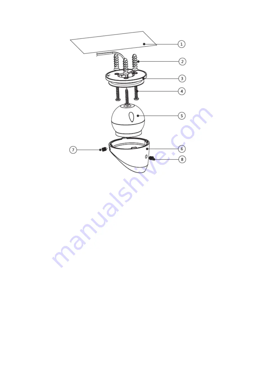
Dahua HAC-HDW3200G-M28 User Manual Download Page 12


Figure 3-3 


Step 1  

Take down the pedestal 

Unscrew the locking screws 

 and 

 anticlockwise to make it separate.  

Step 2  

Take out the installation position map from the device accessories bag, paste it on the 

installation surface 

, and then dig holes on the installation surface according to the 

installation position map.  

Step 3  

Use tools to fix the expansion bolts 

 into the installation holes.  

Step 4  

Adjust pedestal location (if it is side cable outlet, you can pull out the cable through the side 

cable slot). Align the bolt fixing holes of the device pedestal with the expansion bolt fixing holes 

on the installation surface; insert the self-tapping screws 

 into the expansion bolts and 

secure them firmly to make pedestal fixed on the installation surface (if it is top cable outlet, 

you can pull out the cable through the cable outlet on the installation surface after fixing the 

pedestal). 

Step 5  

Install dome body 

 and enclosure 

.  

Put the enclosure into the pedestal together with the dome body, insert locking screws 

clockwise and fix them preliminarily; rotate enclosure and dome body to an appropriate 

monitoring location; finally tighten the locking screws firmly.  

Summary of Contents for HAC-HDW3200G-M28

Page 1: ...HDCVI Camera User s Manual Version 1 0 0 ...

Page 2: ... 3 Installation 6 3 1 Installation for Model A 6 3 2 Installation for Model B 7 3 3 Installation for Model C 9 3 4 Installation for model D 10 3 4 1 Installation for Model D1 with clamping jaw 10 3 4 2 Installation for Model D2 and D3 with bracket 11 4 Menu 12 4 1 HCVR Settings 12 4 2 Menu Operation 12 Appendix Ⅰ Maintenance 14 ...

Page 3: ... the plug power socket and the junction from the device 2 Environment Please don t aim the device at strong light such as lighting sunlight and so on to focus Please transport use and store the device within the range of allowed humidity and temperature Please do not allow water and other liquid falling into the camera in case that the internal components are damaged Please keep the sound ventilat...

Page 4: ... manual will be regularly upgraded according to the product update the upgraded content will be added in the manual without prior announcement Please contact the customer service for the latest procedure and supplementary documentation The company is not liable for any loss caused by the operation which is not followed by the manual Please refer to the company s final explanation if there is any d...

Page 5: ...oaxial transmission without any loss the distance is over 800m for 1080P series it supports RG59 coaxial transmission without any loss the distance is over 500m High speed long distance real time transmission Support HD SD video output some devices only support HD video output Support OSD menu adjusting parameters Support auto exposure AWB auto electronic gain Support true WDR function the range c...

Page 6: ...2 2 Device Structure 2 1 Dimension Refer to Figure 2 1 Figure 2 2 and Figure 2 3 for the dimension of model A The unit is mm Figure 2 1 Figure 2 2 Figure 2 3 ...

Page 7: ... Figure 2 4 Refer to Figure 2 5 for the dimension of model C The unit is mm Figure 2 5 Refer to Figure 2 6 for the dimension of model D1 The unit is mm Figure 2 6 Refer to Figure 2 7 and Figure 2 8 for the dimension of model D2 and model D3 The unit is mm Figure 2 7 ...

Page 8: ...erent devices may have different cables please refer to the actual device for more details Please refer to Figure 2 9 for DC 12V power input port Figure 2 9 Please refer to Figure 2 10 for video output port Figure 2 10 Please refer to Figure 2 11 for audio input port Figure 2 11 Please refer to Figure 2 12 for HD SD switch control cable ...

Page 9: ... realize from HD video output to SD video output On the contrary it will switch back to HD video output when the two cables become open circuit HD SD switch control cable is only supported by some models Please refer to Figure 2 13 for the mobile aviation port Figure 2 13 ...

Page 10: ...et is in accordance with that of the installation position map when sticking the installation position map Besides pull the cable through the pedestal cable slot before locking the screw Please do not remove the electrostatic adsorption film if yes on the surface of transparent cover before installation and debugging is completed which is to avoid damage during installation The installation figure...

Page 11: ...ect the video output port of device cable to the rear end HCVR device and connect the power port to power So far the device installation and cable connection have been completed you can check monitoring image via rear end coding device 3 2 Installation for Model B Model B mainly adopts ceiling installation mode the installation location includes ceiling and wall or it can be installed on the inter...

Page 12: ...ough the side cable slot Align the bolt fixing holes of the device pedestal with the expansion bolt fixing holes on the installation surface insert the self tapping screws into the expansion bolts and secure them firmly to make pedestal fixed on the installation surface if it is top cable outlet you can pull out the cable through the cable outlet on the installation surface after fixing the pedest...

Page 13: ...back end HCVR device So far the device installation and cable connection have been completed you can check monitoring image via rear end coding device 3 3 Installation for Model C Model C can be installed on the vehicle operation platform vehicle tail or it can be hung on the ceiling inside the vehicle Figure 3 5 ...

Page 14: ...o make bracket fixed on the installation board Step 4 Install device body Adjust device body to a proper location and fix it on the bracket finally tighten the fixing screw on the bracket firmly Step 5 Connect the device cable to the back end HCVR device So far the device installation and cable connection have been completed you can check monitoring image via rear end coding device 3 4 Installatio...

Page 15: ...7 Step 1 Use tool to fix the expansion bolts on the installation board Step 2 Adjust the bracket location Align the bolt fixing holes of device bracket with the fixing holes of expansion bolts on the installation board insert the installation screws into the expansion bolts and lock them firmly which is to fix the bracket on the installation board Step 3 Adjust the camera body to a proper position...

Page 16: ...nu Setting System PTZ you need to select the channel number for access and set control mode as HDCVI and the protocol as HD CVI Click Save button to save current setup See Figure 4 1 Figure 4 1 4 2 Menu Operation Click the right mouse button and select PTZ Control then you will see the PTZ Setup menu which is as shown in Figure 4 2 and Figure 4 3 Figure 4 2 ...

Page 17: ...u Select menu item Select menu value Table 4 1 If there is click the Enter button in Menu Operation interface to go to the 2nd menu Click Return button to go back to the previous menu interface Please use a UTC controller or enter the OSD menu for switchover between HD and SD video output ...

Page 18: ... to wipe from the lens center to outward It is ok to change the cloth and wipe several times if it is not clean enough Camera Body Maintenance Use a soft dry cloth to clean the camera body when it is dirty in case the dirt is hard to remove use a clean dry cloth soaked with mild detergent and wipe gently make it dry later Don t use volatile solvent like alcohol benzene thinner and etc or strong de...

Reviews: