


69
USB port
To connect USB storage device, USB mouse.
Network
abnormal
indicator light
Net
Network error occurs or there is no network connection, the
light becomes red to alert you.
HDD
abnormal
indicator light
HDD
HDD error occurs or HDD capacity is below specified
threshold value, the light becomes red to alert you.
Record light
1-16
System is recording or not. It becomes on when system is
recording.
IR Receiver
IR
It is to receive the signal from the remote control.
2.1.6
NVR21HS-S2/21HS-P-S2/21HS-8P-S2/41HS-4KS2/41HS-P-4KS2/41HS-8P-4KS2/
1AHS/1A HS-4P/1AHS-8P/21HS-4KS2/21HS-P-4KS2/21HS-8P-4KS2 Series
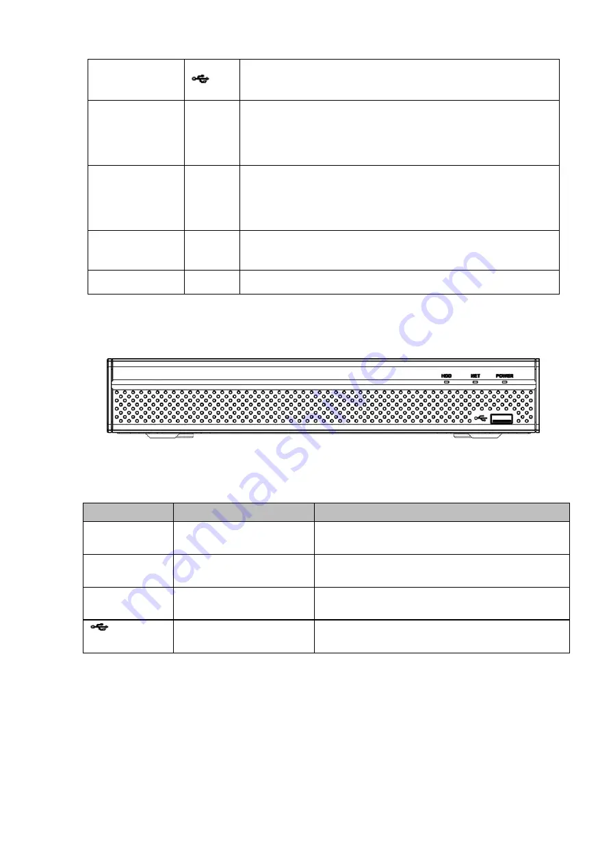
The front panel is shown as below. See Figure 2-6.
Figure 2-6
Please refer to the following sheet for front panel button information.
Icon
Name
Function
HDD
HDD status indicator
light
The blue light is on when the HDD is malfunction.
NET
Network status indicator
light
The blue light is on when the network connection is
abnormal.
POWER
Power status indicator light The blue light is on when the power connection is
OK.
USB port
Connect to peripheral USB storage device, mouse
and etc.
2.1.7
NVR/22-S2/22-P-S2/22-8P-S2/42-16P/42N/52-4KS2/52-8P-4KS2/52-16P-4KS2/42-
4KS2/42-P-4KS2/42-8P-4KS2/42-16P-4KS2/5224-24P-4KS2/54-4KS2/54-16P-4KS
2/44-4KS2/44-16P-4KS2/5424-24P-4KS2/58-4KS2/S258-16P-4KS2/48-4KS2/48-16
P-4KS2/2A16/22-4KS2-22-P-4KS2-22-8P-4KS2/52-16P-4KS2E/54-16P-4KS2E/58-
16P-4KS2E Series
The
NVR22-S2/NVR22-P-S2/22-8P-S2/42-16P/42N/52-4KS2/52-8P-4KS2/52-16P-4KS2/42-4KS2/42-P-4KS
2/42-8P-4KS2/42-16P-4KS2/5224-24P-4KS2/2A16/22-4KS2/22-P-4KS2/22-8P-4KS2/52-16P-4KS2E ser
Summary of Contents for DHI-NVR5224-24P-4KS2
Page 1: ...Network Video Recorder User s Manual V4 3 2...
Page 136: ...124 Figure 3 5 3 6 6 NVR42N Series Please refer to Figure 3 6 for connection sample Figure 3 6...
Page 140: ...128 Figure 3 11 3 6 12 NVR42V 8P Series Please refer to Figure 3 12 for connection sample...
Page 141: ...129 Figure 3 12...
Page 155: ...143 Figure 4 15 Step 2 Click device display edit interface See Figure 4 16...
Page 218: ...206 Figure 4 93 Figure 4 94...
Page 238: ...226 Figure 4 110 Figure 4 111 Figure 4 112...
Page 249: ...237 Figure 4 123 Figure 4 124...
Page 251: ...239 Figure 4 126 Click draw button to draw the zone See Figure 4 127...
Page 255: ...243 Figure 4 130 Click Draw button to draw a zone See Figure 4 131 Figure 4 131...
Page 260: ...248 Figure 4 136 Click draw button to draw the zone See Figure 4 137...
Page 273: ...261 Figure 4 148 Figure 4 149...
Page 274: ...262 Figure 4 150 Figure 4 151...
Page 384: ...372 Figure 5 60 Figure 5 61...
Page 385: ...373 Figure 5 62 Figure 5 63...
Page 409: ...397 Figure 5 96 Figure 5 97...