


337
Figure 5-14
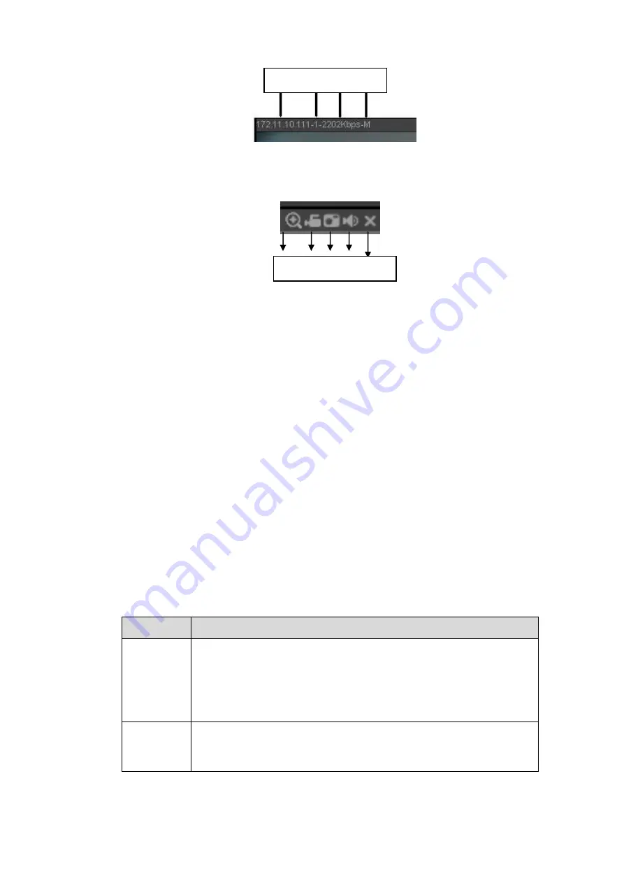
On the top right corner, there are six unction buttons. See Figure 5-15.
Figure 5-15
1: Digital zoom: Click this button and then left drag the mouse in the zone to zoom in. right click
mouse system restores original status.
2: Local record. When you click local record button, the system begins recording and this button
becomes highlighted. You can go to system folder RecordDownload to view the recorded file.
3: Snapshot picture. You can snapshot important video. All images are memorized in system client
folder PictureDownload (default).
4: Audio :Turn on or off audio.(It has no relationship with system audio setup )
5: Close video.
5.6 PTZ
Before PTZ operation, please make sure you have properly set PTZ protocol. (Please refer to chapter
There are eight direction keys. In the middle of the eight direction keys, there is a 3D intelligent
positioning key.
Click 3D intelligent positioning key, system goes back to the single screen mode. Drag the mouse in the
screen to adjust section size. It can realize PTZ automatically.
Please refer to the following sheet for PTZ setup information.
Parameter Function
Scan
Select Scan from the dropdown list.
Click Set button, you can set scan left and right limit.
Use direction buttons to move the camera to you desired location
and then click left limit button. Then move the camera again and
then click right limit button to set a right limit.
Preset
Select Preset from the dropdown list.
Turn the camera to the corresponding position and Input the
preset value. Click Add button to add a preset.
1 2 3 4 5
1 2 3 4
Summary of Contents for DHI-NVR5224-24P-4KS2
Page 1: ...Network Video Recorder User s Manual V4 3 2...
Page 136: ...124 Figure 3 5 3 6 6 NVR42N Series Please refer to Figure 3 6 for connection sample Figure 3 6...
Page 140: ...128 Figure 3 11 3 6 12 NVR42V 8P Series Please refer to Figure 3 12 for connection sample...
Page 141: ...129 Figure 3 12...
Page 155: ...143 Figure 4 15 Step 2 Click device display edit interface See Figure 4 16...
Page 218: ...206 Figure 4 93 Figure 4 94...
Page 238: ...226 Figure 4 110 Figure 4 111 Figure 4 112...
Page 249: ...237 Figure 4 123 Figure 4 124...
Page 251: ...239 Figure 4 126 Click draw button to draw the zone See Figure 4 127...
Page 255: ...243 Figure 4 130 Click Draw button to draw a zone See Figure 4 131 Figure 4 131...
Page 260: ...248 Figure 4 136 Click draw button to draw the zone See Figure 4 137...
Page 273: ...261 Figure 4 148 Figure 4 149...
Page 274: ...262 Figure 4 150 Figure 4 151...
Page 384: ...372 Figure 5 60 Figure 5 61...
Page 385: ...373 Figure 5 62 Figure 5 63...
Page 409: ...397 Figure 5 96 Figure 5 97...