


233
The object total size shall not be more than 10% of the whole video.
The object size on the video shall not be more than 10pixels*10 pixels. The abandoned object size
shall be more than 15pixels*15 pixels (CIF resolution). The object width shall not be more than 1/3 of
the video height and width. The recommended height is 10% of the video.
The object and the background brightness different shall be more than 10 grey levels.
The object shall remain on the video for more than 2 seconds. The moving distance is larger than its
own width and shall not be smaller than 15pixels (CIF resolution).
The surveillance environment shall not be too complicated. The IVS function is not suitable for the
environment of too many objects or the changing light.
The surveillance environment shall not contain glasses, reflection light from the ground, and water.
Free of tree branches, shadow, mosquito and bugs. Do not use the IVS function in the backlight
environment, avoid direct sunlight.
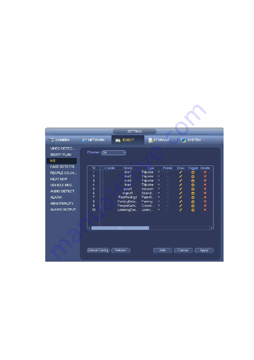
From main menu->Setting->Event->Behavior Analytics, you can go to the behavior analytics interface.
Here you can set general behavior analytics rule. System can generate an alarm as the mode you
previously set once there is any object violates the rule. See Figure 4-119.
Figure 4-119
Select a channel from the dropdown list.
Click Add button to add a rule and then select a rule type from the dropdown list.
Set corresponding parameters.
Click Apply button to complete the setup.
4.7.3.1 Tripwire (Optional)
System generates an alarm once there is any object crossing the tripwire in the specified direction.
The tripwire supports customized setup. It can be a straight line or a curve.
Support one-direction or dual-direction detection.
Summary of Contents for DHI-NVR5224-24P-4KS2
Page 1: ...Network Video Recorder User s Manual V4 3 2...
Page 136: ...124 Figure 3 5 3 6 6 NVR42N Series Please refer to Figure 3 6 for connection sample Figure 3 6...
Page 140: ...128 Figure 3 11 3 6 12 NVR42V 8P Series Please refer to Figure 3 12 for connection sample...
Page 141: ...129 Figure 3 12...
Page 155: ...143 Figure 4 15 Step 2 Click device display edit interface See Figure 4 16...
Page 218: ...206 Figure 4 93 Figure 4 94...
Page 238: ...226 Figure 4 110 Figure 4 111 Figure 4 112...
Page 249: ...237 Figure 4 123 Figure 4 124...
Page 251: ...239 Figure 4 126 Click draw button to draw the zone See Figure 4 127...
Page 255: ...243 Figure 4 130 Click Draw button to draw a zone See Figure 4 131 Figure 4 131...
Page 260: ...248 Figure 4 136 Click draw button to draw the zone See Figure 4 137...
Page 273: ...261 Figure 4 148 Figure 4 149...
Page 274: ...262 Figure 4 150 Figure 4 151...
Page 384: ...372 Figure 5 60 Figure 5 61...
Page 385: ...373 Figure 5 62 Figure 5 63...
Page 409: ...397 Figure 5 96 Figure 5 97...