


97
Name
Function
MIC IN
Audio input port
Bidirectional talk input port. It is to receive the analog
audio signal output from the devices such as
microphone, pickup.
MIC OUT
Audio output port Audio output port. It is to output the analog audio signal
to the devices such as the sound box.
Bidirectional talk output.
Audio output on 1-window video monitor.
Audio output on 1-window video playback.
1
~
2
Alarm input port
1
~
2
When your alarm input device is using external
power, please make sure the device and the NVR
have the same ground.
GND
Alarm input ground port.
C
Alarm
output
public port
Alarm output public end.
NO
Normal open
Normal open alarm output port.
Network port
10M/100M/1000Mbps self-adaptive Ethernet port.
Connect to the network cable.
USB3.0 port
USB3.0 port. Connect to mouse, USB storage device,
USB burner and etc.
HDMI
High
Definition
Media Interface
High definition audio and video signal output port. It
transmits uncompressed high definition video and
multiple-channel data to the HDMI port of the display
device. HDMI version is 1.4.
VGA
VGA
video
output port
VGA video output port. Output analog video signal. It
can connect to the monitor to view analog video.
PoE
PORT
/
Bult-in Switch. Support PoE.
The 8 PoE series product supports total 48V 120W.
One PoE port max supports 15W.
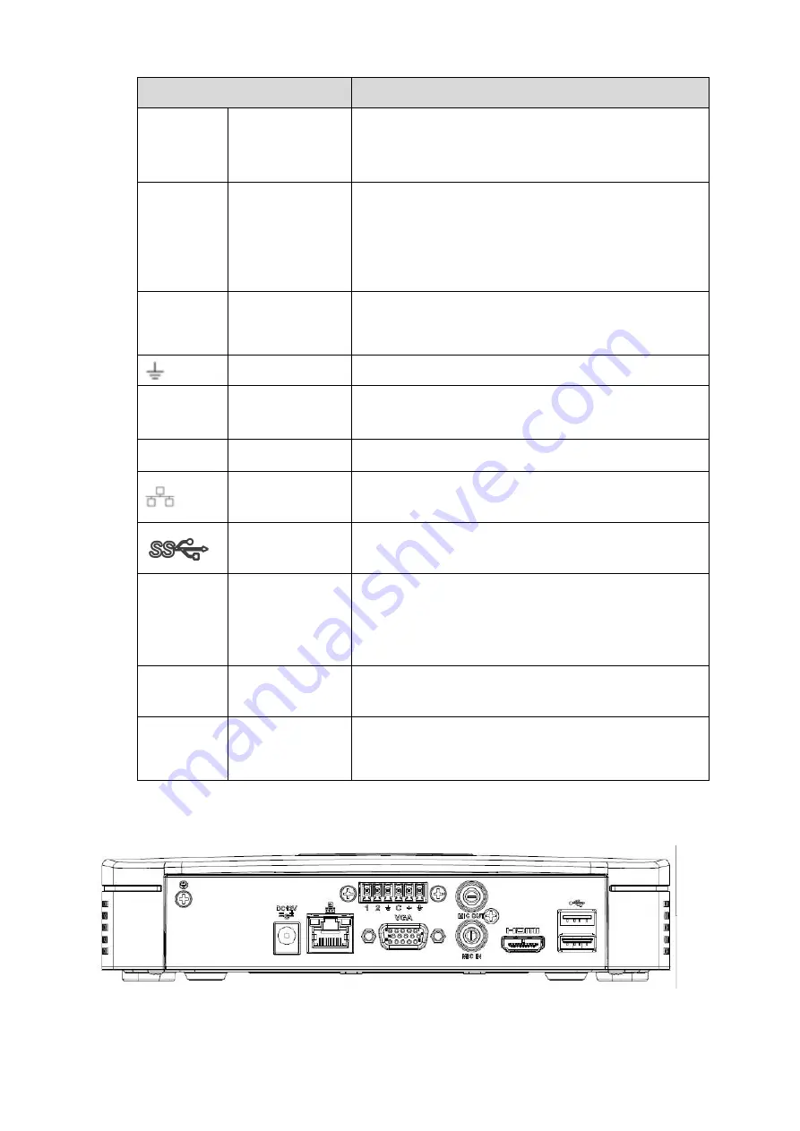
2.2.13
NVR41-4KS2/41-P-4KS2/41-8P-4KS2
The NVR41-4KS2 series rear panel is shown as below. See Figure 2-51.
Figure 2-51
The NVR41-P-4KS2 series rear panel is shown as below. See Figure 2-52.
Summary of Contents for DHI-NVR5224-24P-4KS2
Page 1: ...Network Video Recorder User s Manual V4 3 2...
Page 136: ...124 Figure 3 5 3 6 6 NVR42N Series Please refer to Figure 3 6 for connection sample Figure 3 6...
Page 140: ...128 Figure 3 11 3 6 12 NVR42V 8P Series Please refer to Figure 3 12 for connection sample...
Page 141: ...129 Figure 3 12...
Page 155: ...143 Figure 4 15 Step 2 Click device display edit interface See Figure 4 16...
Page 218: ...206 Figure 4 93 Figure 4 94...
Page 238: ...226 Figure 4 110 Figure 4 111 Figure 4 112...
Page 249: ...237 Figure 4 123 Figure 4 124...
Page 251: ...239 Figure 4 126 Click draw button to draw the zone See Figure 4 127...
Page 255: ...243 Figure 4 130 Click Draw button to draw a zone See Figure 4 131 Figure 4 131...
Page 260: ...248 Figure 4 136 Click draw button to draw the zone See Figure 4 137...
Page 273: ...261 Figure 4 148 Figure 4 149...
Page 274: ...262 Figure 4 150 Figure 4 151...
Page 384: ...372 Figure 5 60 Figure 5 61...
Page 385: ...373 Figure 5 62 Figure 5 63...
Page 409: ...397 Figure 5 96 Figure 5 97...