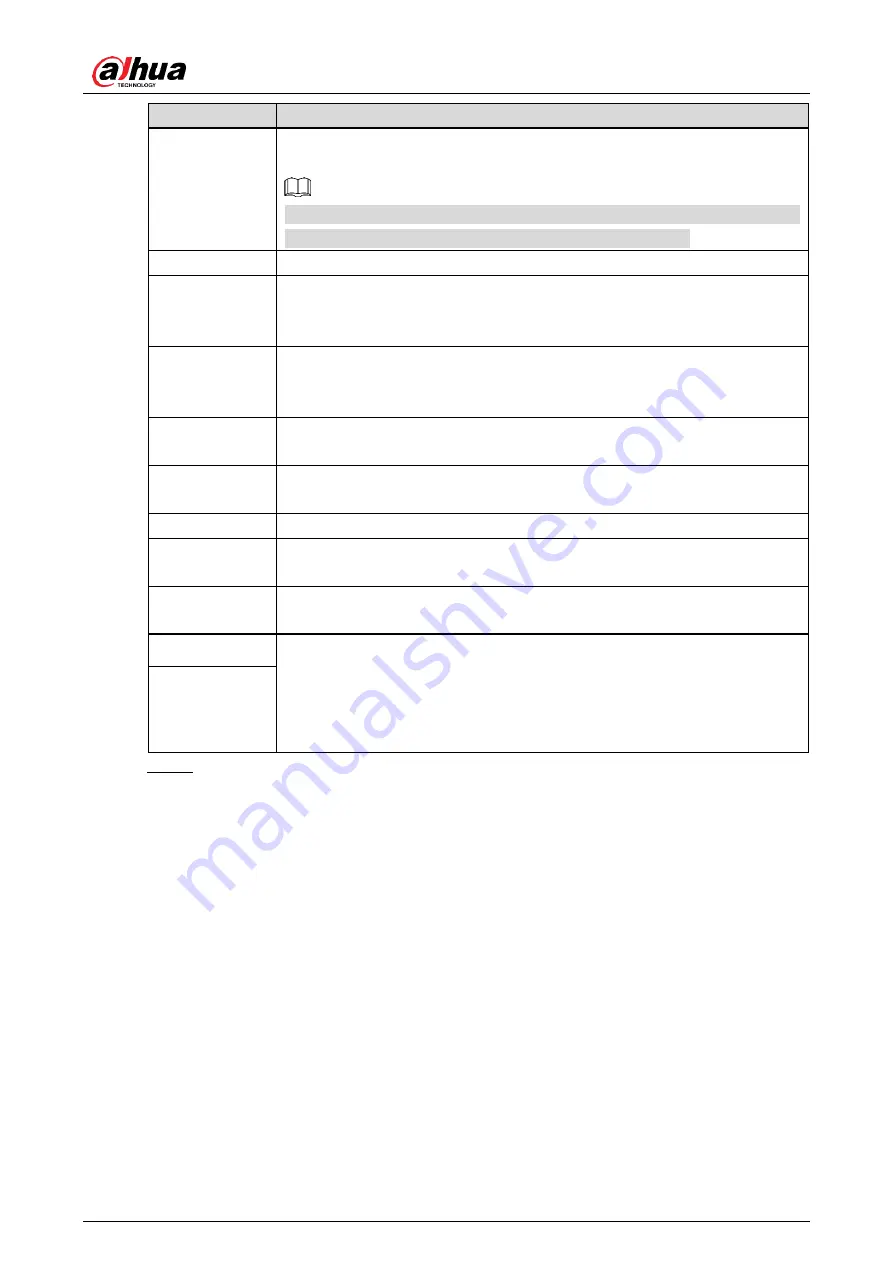
background image

User’s Manual


Parameter 

Description 

Work Mode 

The way of sending information captured by the Radar. You can select 

Single

Continuous

 or 

Manual


Currently, camera supports only 

Single

. Special program is required if you 

want to send the information in continuous or manual way. 

Interval 

The interval that the Radar detects and recognizes an object. 

Detect Mode 

The detection direction of the Radar, which includes 

Approaching

Departing

, and

 Both

. Select according to the actual installation status of 

the Radar. 

Angle 

The elevation angle, means the the angle between the normal line of the 

radar front cover and the horizontal line. Properly adjust the angle to get 

best detection result. 

Sensitivity 

You can select the capture sensitivity of the Radar. The larger the value, 

the more sensitive the Radar. 

Trigger Speed 

Capture will be triggered when the vehicle speed reaches the defined 

trigger speed. 

Radar No. 

The No. that defines the Radar. 

Trigger 

Distance 

The distance that triggers capture. Enter the value according to the actual 

trigger distance of the Radar. 

Height 

Installation height of the Radar. Enter the height according to the actual 

installation height of the Radar. 

Pre Speed Wait  The two parameters help get the vehicle speed. By video detection or 

radar, the camera can detect the vehicle speed. If vehicle speed is 

detected within the range of 

Pre Speed Wait

 and 

Delay Speed Wait

, then 

such speed will be the vehicle speed recognized by the Camera; if out of 

such range, then the speed will be a random value within speed limit. 

Delay Speed 

Wait 

  Click 

Confirm

Step 5

Summary of Contents for DHI-ITARD-024SA-ST

Page 1: ...24 GHz Radar Detector User s Manual V1 0 0 V1 0 0 ZHEJIANG DAHUA VISION TECHNOLOGY CO LTD ZHEJIANG DAHUA VISION TECHNOLOGY CO LTD...

Page 2: ...des methods to help you solve a problem or save you time Provides additional information as the emphasis and supplement to the text Revision History Version Revision Content Release Time V1 0 0 First...

Page 3: ...re is any doubt or dispute please refer to our final explanation Upgrade the reader software or try other mainstream reader software if the manual in PDF format cannot be opened All trademarks registe...

Page 4: ...ower supply is correct before operating the Radar Use power supply that meets SELV safety extra low voltage requirements and supply power with rated voltage that conforms to Limited Power Source in IE...

Page 5: ...V Maintenance Requirements WARNING Use accessories suggested by the manufacturer and install and maintain the Radar by professionals Do not provide two or more power supply modes otherwise the Radar m...

Page 6: ...Introduction 1 Overview 1 1 1 Features 1 1 2 2 Device Structure 2 Dimensions 2 2 1 Structure 2 2 2 Cable 4 2 3 3 Installation 5 Fixing the Radar to Brackets 5 3 1 Installing the Radar above Lane 6 3...

Page 7: ...l time traffic information and forensic evidence for traffic speed violations Features 1 2 Adopts 24 GHz MMIC technology light weighted and efficient High precision capture at fixed position Position...

Page 8: ...s Manual 2 2 Device Structure Dimensions 2 1 Front view mm inch Figure 2 1 Side view mm inch Figure 2 2 Structure 2 2 The device structure relates to the Radar and the bracket See Figure 2 3 and Figur...

Page 9: ...ble 2 1 Radar structure No Description No Description 1 Antenna 4 Set screw 2 Sealing washer 5 PG connector 3 Front cover 6 Rear cover Bracket structure Figure 2 4 Table 2 2 Bracket structure No Descr...

Page 10: ...er supply 2 12V DC red Pin for 12V radar power supply 3 TXD green TX pin for radar RS 232 communication baud rate 9600 connects to R1 R2 and R3 ports of camera 4 RXD yellow RX pin for radar RS 232 com...

Page 11: ...3 1 The brackets help fix the Radar and adjust the angle of the Radar Fix bracket 1 to the Radar with four M6 8 hex socket cap screws Step 1 Fix bracket 1 Figure 3 1 Fix bracket 2 to bracket 1 with fo...

Page 12: ...tion of the detected lane Step 2 Adjust Radar position Figure 3 4 Adjust the installation height elevation angle the angle between the normal line of the Step 3 radar front cover and the horizontal li...

Page 13: ...User s Manual 7 Radar installation example Figure 3 5...

Page 14: ...Select Setup ITC Intelligent Radar Step 3 Radar Figure 4 1 Select Enable Radar to enable radar detection and then you can configure the Step 4 parameters This section takes ITARD 024SA ST radar as an...

Page 15: ...sitivity You can select the capture sensitivity of the Radar The larger the value the more sensitive the Radar Trigger Speed Capture will be triggered when the vehicle speed reaches the defined trigge...

Page 16: ...cted is fully covered by the radar beam Check whether the elevation angle of the Radar is reasonable Check whether the sensitivity is set too low The Radar detects vehicle speed but does not capture v...

Page 17: ...able the auto check for updates function to obtain timely information of firmware updates released by the manufacturer We suggest that you download and use the latest version of client software Nice t...

Page 18: ...services SNMP Choose SNMP v3 and set up strong encryption passwords and authentication passwords SMTP Choose TLS to access mailbox server FTP Choose SFTP and set up strong passwords AP hotspot Choose...

Page 19: ...sted to use VLAN network GAP and other technologies to partition the network so as to achieve the network isolation effect Establish the 802 1x access authentication system to reduce the risk of unaut...

Page 20: ...User s Manual...

Page 21: ...interference when the equipment is operated in a commercial environment This equipment generates uses and can radiate radio frequency energy and if it is not installed and used in accordance with the...

Reviews: