User’s Manual
64
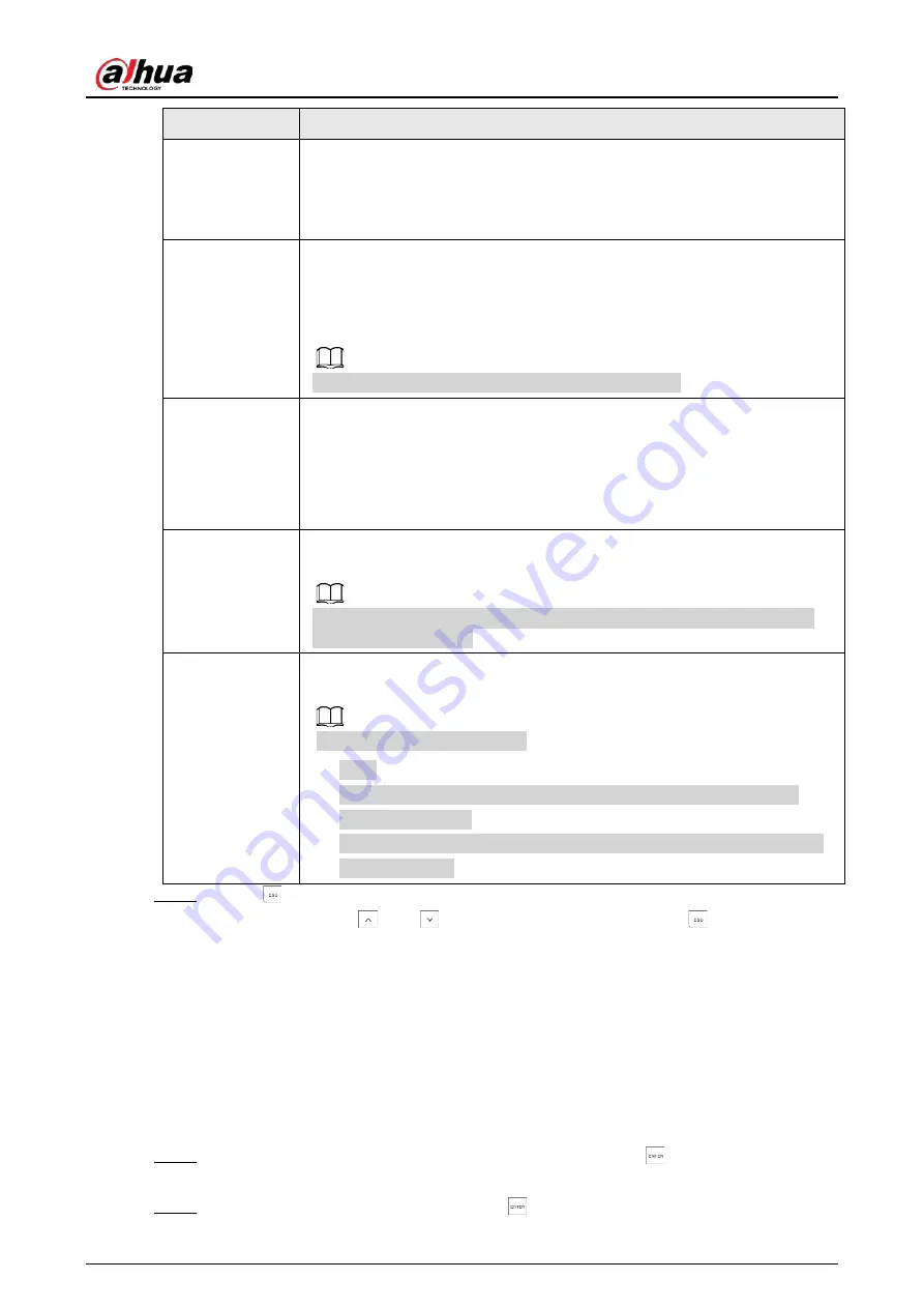
Submenu
Setting
ZONE STATUS
Establish whether the access code can change the zone status, for example,
from
ACTIVE
to
DISALED
.
●
YES
●
NO
REMOTE
Establish whether the access code can control the controller through call and
SMS.
●
YES
●
NO
Controlling through app is not affected by this setting.
TIMER
Establish whether the access code is limited to operation only during certain
time period.
There are four timers can be given to the access code, and each timer can
select from eight timers that are configured in the system. If you select 0, the
access code can operate during the whole period instead of limited time
period.
LINK 1, 2, 3, 4
Establish whether the access code has the authorization to activate
command outputs (maximum 4) and the number of outputs to be activated.
This function is valid only when the Link type is selected in the
OUTPUTS
menu of installer menu.
NEW CODE
Enter a new code that contains 4 to 6 digits. It cannot start with 0. For details,
see "7.14.3 Configuring Access Codes".
Following codes cannot be set.
●
1234.
●
Previous code. For example, if you used 1235 as a code before, you
cannot use it again.
●
Previous code + 1. For example, if you used 1235 as a code before, you
cannot use 1236.
Step 5
Press
to return to the
ACCESS CODES
menu.
Then you can press
and
to move to the next menu or press
to exit from the
installer menu.
7.14.3 Configuring Access Codes
7.14.3.1 Setting an Access Code
If you want to set or change an access code, follow the steps described in "7.14.2 Configuring
Authority Level" to enter the
NEW CODE
submenu.
Step 1
On the
NEW CODE
menu, enter the new code, and then press
.
The confirmation text
PWD VALID
is displayed.
Step 2
Enter the new code again, and then press
to save the new code.
Summary of Contents for DHI-ARC3008C
Page 1: ...Alarm Controller User s Manual ZHEJIANG DAHUA VISION TECHNOLOGY CO LTD V2 0 1...
Page 25: ...User s Manual 14 2 4 Wiring Figure 2 6 Wiring Figure 2 7 Wiring of detectors...
Page 31: ...User s Manual 20 4 3 Wiring Figure 4 3 keypad connection...
Page 41: ...User s Manual 30 5 2 Wiring Figure 5 2 Wiring of detectors...
Page 45: ...User s Manual 34 Figure 6 2 Remove plugs Step 2 Attach the thermal pad to the 4G module...
Page 137: ...User s Manual...


