background image


Web  Interface


85 


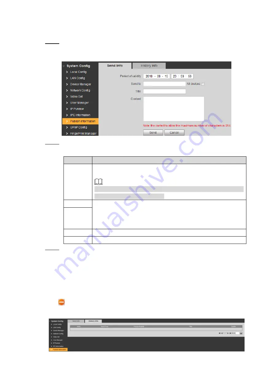
7.11.1 Send Info 

  Select 

System Config > Publish Information > Send Info

Step 1

The 

Send Info

 interface is displayed. See Figure 7-40. 

 Send Info 

Figure 7-40


  Configure send info parameters. See Table 7-17 for the details. 

Step 2

Table 7-17 Send info parameter description 

Parameter  Description 

Period of 

validity 

Send the information before the 

Period of validity

, otherwise, the 

VTH users can not receive the information. 


All the sent information would display in the 

History Info

 whether the 

VTH users received them or not. 

Send to 

The information receiver. 


If you need to send to single user, input his room number. 


If you need to send to all the users, select the 

All devices

 check 

box. 

All devices   

Title 

The title of the information. 

Content 

256 character’s at most. 

  Click 

Send

Step 3

The information is sent to the VTH users. 

7.11.2 History Info 

Select 

System  Config  >  Publish  Information  >  History  Info

,  and  then  the 

History  Info


interface is displayed, see Figure 7-41. 

Click 

  to delete publish history. 

 History Info 

Figure 7-41


Summary of Contents for DH-VTO9341D

Page 1: ...Face Recognition Apartment Outdoor Station User s Manual V1 0 0...

Page 2: ...ns to improve your network security Change Passwords Regularly Regularly change the credentials to your devices to help ensure that only authorized users are able to access the system Change Default H...

Page 3: ...lted you may end up with unwanted visitors If you manually forwarded the HTTP and TCP ports in your router modem this feature should be turned off regardless Disabling UPnP is recommended when the fun...

Page 4: ...ructions may cause harmful interference to radio communication For class A device these limits are designed to provide reasonable protection against harmful interference in a commercial environment Op...

Page 5: ...ods to help you solve a problem or save you time NOTE Provides additional information as the emphasis and supplement to the text Revision History No Version Revision Content Release Date 1 V1 0 0 Firs...

Page 6: ...actual product and the Manual Please contact the customer service for the latest program and supplementary documentation There still might be deviation in technical data functions and operations desc...

Page 7: ...lug power socket and the junction extruded from the device We assume no liability or responsibility for all the fires or electrical shock caused by improper handling or installation Environment Do not...

Page 8: ...e VTO 11 Installation Requirement 11 4 1 Connecting Cable 11 4 2 Attaching the VTO 11 4 3 5 Configuring Devices 13 Configuration 13 5 1 5 1 1 Configuring VTO 13 5 1 2 Configuring VTH 20 Verifying Conf...

Page 9: ...VTO 58 7 1 Login 59 7 2 System Config 60 7 3 7 3 1 Local Config 60 7 3 2 A C Manager 61 7 3 3 Talk Manager 62 7 3 4 System Time 63 7 3 5 Config Manager 64 7 3 6 Wiegand 65 LAN Config 65 7 4 7 4 1 LAN...

Page 10: ...ice 88 Fingerprint Manager 88 7 13 7 13 2 Adding Fingerprint 88 7 13 3 Modifying Fingerprint 89 7 13 4 Deleting Fingerprint 89 7 13 5 Export Fingerprint 89 7 13 6 Import Fingerprint 89 Face Management...

Page 11: ...areas together with a management server it can provide overall burglar proof disaster prevention and security surveillance Features 1 2 Video Intercom Make video call with the management center or VT...

Page 12: ...orts various alarms including tamper alarm door contact alarm and duress password alarm The alarm will also be sent to the management center Information Publishing The VTO can send information to mult...

Page 13: ...Appearance 3 2 Appearance Dimension 2 1 See Figure 2 1 for the dimension Dimension unit mm Figure 2 1 Front Panel 2 2 See Figure 2 2 for the front panel and for the detailed description see Table 2 1...

Page 14: ...ight Provides extra light when recognizing faces Provides extra light to the camera during dark condition 5 Screen 10 Inch IPS HD screen 6 Access card area Issues access card which is giving an access...

Page 15: ...t is being removed from the wall by force and the alarm will also be sent to the management center 3 Power port Inputs power to the VTO 4 USB debugging port Connects to debugging devices 5 Reset butto...

Page 16: ...can be used to connect to door locks and the connection method varies with different locks For the detailed information see Figure 2 4 Figure 2 5 and Figure 2 6 Electro mechanical lock connection Fig...

Page 17: ...on method see Figure 2 7 485 devices connection Figure 2 7 2 3 3 Wiegand Port This port is reserved which includes one set of input port and one set of output port The Wiegand input port can connect t...

Page 18: ...4 Alarm in Port There are two alarm in ports which can connect to two alarm input devices See Figure 2 9 Alarm input device connection Figure 2 9 2 3 5 Alarm out Port There are two alarm out ports wh...

Page 19: ...Appearance 9 Alarm output device connection Figure 2 10...

Page 20: ...Network Diagram 10 3 Network Diagram See Figure 3 1 for the network diagram of the VTO Network diagram Figure 3 1...

Page 21: ...elter The installation and adjustment must be finished by professional crew and do not disassemble the VTO by yourself Connecting Cable 4 2 For the connection method see 2 3 Rear Panel Attaching the V...

Page 22: ...6 m above the ground Attach the VTO to the mounting box with the screw Step 1 Cut an opening with the size of the mounting box on the wall and then put the Step 2 mounting box and the VTO in the openi...

Page 23: ...O requires VTH devices with SIP system to function and this manual takes configuring the 10 inch model VTH for example You need to configure every VTO and VTH in the network 5 1 1 Configuring VTO 5 1...

Page 24: ...interface and it should contain at least 8 digits and at least two types from number letter and symbol Email setting Figure 5 2 Select the Email check box and then enter your Email address Step 4 This...

Page 25: ...the password and then click Login Step 7 The default username is admin The password is what you configured during initialization 5 1 1 2 Modifying VTO IP Address You can modify the default IP address...

Page 26: ...network to transmit intercom protocol and all the VTO and VTH devices connected to the same SIP server can make video call between each other Select System Config LAN Config and then the LAN Config i...

Page 27: ...P server See Table 5 1 for the configuration and then click OK The VTO reboots and then the login interface is displayed Table 5 1 SIP server config 1 Parameter Description IP Address The IP address o...

Page 28: ...Adding VTO Login the Web interface of the VTO that is configured as SIP server Step 1 Select System Config Device Manager Outdoor Station Manager Step 2 The Outdoor Station Manager interface is displa...

Page 29: ...of the VTO that is configured as SIP server Step 1 Select System Config Device Manager 8001 Indoor Station Manager Step 2 The 8001 Indoor Station Manager interface is displayed see Figure 5 10 8001 in...

Page 30: ...ve repeatedly to add more VTH devices in the network 5 1 2 Configuring VTH 5 1 2 1 Initializing VTH Configure VTH password and link to your Email Password it can be used to go to the engineering inter...

Page 31: ...get information from the VTO In the main interface press and hold Setting until the Password Verification dialog Step 1 box displays Enter the password you configured during initialization and then t...

Page 32: ...i function The Wi Fi networks that have been found are listed See Figure 5 16 Wi Fi list Figure 5 16 2 Connect Wi Fi There are two ways to connect Wi Fi Select the Wi Fi you need in the list and then...

Page 33: ...ap OK Step 2 Tap VTH Config Step 3 The VTH Config interface is displayed See Figure 5 18 VTH Config Figure 5 18 Configure the VTH information Step 1 Configure master VTH Enter the room number such as...

Page 34: ...server information and connect the VTH to the SIP server In the main interface press and hold Setting until the Password Verification dialog Step 1 box displays Enter the password you configured durin...

Page 35: ...onfig interface is displayed See Figure 5 20 VTO Config Figure 5 20 Add VTO or fence station Step 4 If you use single VTO then only enter the VTO information at Main_VTO Name if you use multiple VTO d...

Page 36: ...oom number of the VTH on the VTO Step 1 Tap Call Step 2 The Calling now please wait a moment voice notice comes up and then the calling request lasts for 30 s See Figure 5 21 Calling the VTH Figure 5...

Page 37: ...nfiguration succeeded Phone call state Figure 5 23 5 2 2 Doing monitor from VTH You can monitor the area that VTO covers from VTH In the main interface of the VTH select Monitor Door and then the Door...

Page 38: ...Configuring Devices 28 Monitor screen Figure 5 25...

Page 39: ...ter booting See Figure 6 1 For the detailed description see Table 6 1 Main interface Figure 6 1 Table 6 1 Main interface description Name Description Function list The functions that the residents can...

Page 40: ...r of the VTH on the VTO Step 1 Tap Call Step 2 The Calling now please wait a moment voice notice comes up and then the calling request lasts for 30 s See Figure 6 2 Calling VTH Figure 6 2 The call scr...

Page 41: ...y on the VTO or enter the number of the management center and then tap Step 1 Call The Calling now please wait a moment voice notice comes up and then the calling request lasts for 30 s See Figure 6 5...

Page 42: ...Operating VTO 32 Calling management center Figure 6 5 The management center answers the call Step 2 The VTO is in the phone call state See Figure 6 6 Phone call state Figure 6 6...

Page 43: ...displays after 10 s the unlocking failed and you need to check if the face data was added to the VTO In Main Interface Tap Face Recognition Step 1 Come close and face to the camera Step 2 The VTO star...

Page 44: ...tice comes up if the Card Error notice is displayed and the beep sound comes up you need to check the whether the access card is authorized For the details see 6 4 3 Issuing Card 6 3 5 VTH Unlock VTH...

Page 45: ...n add new face data to the VTO with the authorized access card In the main interface tap Owner Registration Step 1 The Swipe authorized card notice is displayed See Figure 6 8 Swipe authorized card Fi...

Page 46: ...lect Face Add face Step 3 The face recognition interface is displayed The VTO starts face recognition See Figure 6 10 Step 4 To restart the registration tap Cancel Face recognition Figure 6 10 After t...

Page 47: ...er one room number Tap OK to save Step 7 The face data list of this room number is displayed Tap to exit 6 4 1 2 Face Registration by Admin People In the main interface enter VTO password Step 1 The I...

Page 48: ...n Figure 6 12 After the registration finished tap Confirm Step 4 The information registration interface is displayed See Figure 6 13 Information registration Figure 6 13 Enter the room number and name...

Page 49: ...t Registration by VTO Users The VTO users can add new fingerprint data to the VTO with the authorized access card In the main interface tap Owner Registration Step 1 The Swipe authorized card notice i...

Page 50: ...ngerprint Step 3 The fingerprint recognition interface is displayed See Figure 6 16 Fingerprint recognition Figure 6 16 Tap the fingerprint sensor as instructed Step 4 After the registration finished...

Page 51: ...fingerprints at most under one room number Tap OK to save Step 6 Tap to exit 6 4 2 2 Fingerprint Registration by Admin People In the main interface enter VTO password Step 1 The IP Setting interface i...

Page 52: ...ess the fingerprint sensor as instructed Step 3 After the registration finished the information registration interface is displayed See Figure 6 19 Information registration Figure 6 19 Enter the room...

Page 53: ...p 1 The IP Setting interface is displayed Select User Registration Card Password Step 2 The Input password interface is displayed See Figure 6 20 Input password Figure 6 20 Enter the card issuing pass...

Page 54: ...ep 6 Tap repeatedly to exit 6 4 3 2 Issuing Card by Master Card Issuing card by master card is only available on the VTO Before issuing card by master card make sure the master card is available If no...

Page 55: ...er card Figure 6 22 Swipe the master card Step 3 The Enter Room No interface is displayed See Figure 6 23 Enter room number Figure 6 23 Enter the room number and then tap OK Step 4 The Swipe authorize...

Page 56: ...to finish Step 6 Tap repeatedly to exit Viewing Function 6 5 6 5 1 Viewing Face Data 6 5 1 1 Viewing by VTO Users The VTO users can view and maintain the face data under their room number with the au...

Page 57: ...Operating VTO 47 Registration Figure 6 25 Select Face Face Query Step 3 The face data are listed See Figure 6 26 Face data Figure 6 26 Editing face data 1 Tap...

Page 58: ...o you want to delete face info notice is displayed 2 Tap Yes Exiting query interface Tap repeatedly to exit 6 5 1 2 Viewing by Admin People The admin people or engineer can view and maintain the face...

Page 59: ...is finished the information editing interface is displayed 4 Edit room number and name 5 Tap OK to finish Deleting face data 6 Tap The Do you want to delete face info notice is displayed 7 Tap Yes Ex...

Page 60: ...yed See Figure 6 29 Swipe authorized card Figure 6 29 Swipe the authorized card Step 2 The registration interface is displayed See Figure 6 30 Registration Figure 6 30 Select Fingerprint Fingerprint Q...

Page 61: ...int info notice is displayed 2 Tap Yes Exiting query interface Tap repeatedly to exit 6 5 2 2 Viewing by Admin People The admin people can view and maintain the fingerprint data under a certain room n...

Page 62: ...Enter room number Figure 6 32 Enter the room number and then tap OK Step 3 The fingerprint data of this room are listed See Figure 6 33 Fingerprint data Figure 6 33 Maintaining fingerprint Step 4 Edi...

Page 63: ...3 Viewing Card Information You can view the card information on the VTO Web interface or on the server For the viewing operation on the Web interface see 7 5 3 Card Info for the operation on the serve...

Page 64: ...ange the password in the Web interface after the first use See the details in 7 3 2 A C Manager 6 6 2 Configuring the IP Address You can configure the IP address subnet mask and default gateway of the...

Page 65: ...kspace and then tap the numbers to input Step 3 Tap Confirm to save Step 4 The VTO reboots 6 6 3 Configuring Volume Screensaver Time Brightness In the main interface enter VTO password Step 1 The IP S...

Page 66: ...Brightness Time includes the Screensaver Time and the duration of the screensaver and when the Brightness Time ends the VTO screen is off The Brightness Time range is 10 m 300 m Info 6 7 6 7 1 Viewing...

Page 67: ...Operating VTO 57 Info Figure 6 37 6 7 2 Viewing Notices In the main interface tap to view the text notice from the SIP server...

Page 68: ...default IP address of the VTO in the address bar and then press Enter Step 1 The password setting interface is displayed See Figure 7 1 Password setting Figure 7 1 Enter and confirm the password and...

Page 69: ...setting Click Next Step 4 The Device Succeed interface is displayed and the initialization is finished See Figure 7 3 Device succeed Figure 7 3 Click OK Step 5 The login interface is displayed Login...

Page 70: ...re fill light sensitivity storage path shout time device type reboot date and center control number Select System Config Local Config Local Config Step 1 The Local Config interface is displayed See Fi...

Page 71: ...t Main Version Info The version of the VTO system Centre Control Number The number of the management center and it is 888888 by default Click OK to save Step 3 7 3 2 A C Manager This section introduce...

Page 72: ...tocol Select Lift Control Protocol and Lift Control Enable to enable the lift control function and then you can configure the floors that lift users can go to Lift Control Enable Baud Rate Enter the b...

Page 73: ...an enable this function and configure FTP to make it work If the SD card is available the messages will be saved in the SD card by default and this option is invalid Select Enable and then the meaasge...

Page 74: ...ng the system time turn off video recording or auto snapshot Sync PC Click to sync the VTO system time and the PC system time NTP Config Select the check box to enable NTP timing NTP Server Enter the...

Page 75: ...d sensors Select System Config Local Config Wiegand Step 1 The Wiegand interface is displayed See Figure 7 10 Wiegand Figure 7 10 Configure Wiegand parameters See Table 7 5 for the details Step 2 Tabl...

Page 76: ...n VTH would receive the call After turning on or off the group call the configuration takes effect after the VTO reboots Server Type Select the SIP server type If VTO works as SIP server select VTO If...

Page 77: ...irst room number in floor 1 for starter First room of floor 2 Configure the first room number in floor 2 for starter Creat Room No Select Creat Room No and then the VTO can create numbers in batch wit...

Page 78: ...he Support Building is enabled Building Unit No Configure the number of the building unit that the VTO is being installed This option is editable only when third party server works as SIP server and t...

Page 79: ...nfig Device Manager 8001 Indoor Station Manager and then the 8001 Indoor Station Manager interface is displayed See Figure 7 15 8001 indoor station manager Figure 7 15 7 5 2 1 Adding VTH Click Add Ste...

Page 80: ...7 17 Modifying VTH Figure 7 17 Modify all the parameters of the VTH See Table 7 9 Step 2 Click OK to finish Step 3 7 5 2 3 Deleting VTH Click to delete VTH one by one click Clear to delete all the VT...

Page 81: ...t and the card is valid again 7 5 3 3 Modifying Card Click Step 1 The Modify interface is displayed See Figure 7 19 Modifying card username Figure 7 19 Modify the card username Step 2 Click OK Step 3...

Page 82: ...rd and then click OK Step 3 The PC downloads the file automatically Step 4 Import Config Import the local config files into a VTO to apply the config Click Import Config Step 1 The File Upload interfa...

Page 83: ...P server and then you can save the recorded videos and snapshots to the FTP server You need to plan the FTP server in advance Select System Config Network Config FTP Config Step 1 The FTP Config inter...

Page 84: ...Description IP Address The IP address of the VTO that works as SIP server Port It is 5060 by default Username Leave to the default Password SIP Domain The SIP Domain is VDP Username The username and p...

Page 85: ...t is changed enter http VTO IP address web port in the address bar of the Internet browser to login the Web interface of the corresponding VTO 7 6 5 DDNS Config Properly configure DDNS and then you ca...

Page 86: ...provide You need to register an account with user name and password on the DDNS service provides website Password DDNS Live Time The time interval that the VTO syncs IP address with the DDNS server To...

Page 87: ...l be Bit Rate Configure the data amount that transmitted in 1 second You can select from 256Kbps 1Mbps 2Mbps and 3Mbps The larger the value is the better the video quality will be Brightness Changes t...

Page 88: ...on the system constrains bright areas and reduces halo size to dim the overall brightness Mirror Select On and then the image would display with left and right side reversed Flip Select On and then th...

Page 89: ...two types from number letter and symbol Click OK to finish configuration Step 3 7 8 2 Modifying User 7 8 2 1 Modify Admin User The admin user can modify his own password and email address The email a...

Page 90: ...users except the admin user Admin user can modify all the uses information and password while normal users can only modify their own This Manual takes admin user as example Click in the normal user i...

Page 91: ...re access authority White list only the IP addresses in the list can login the VTO Black list all the IP addresses in the list are prohibited from login the VTO If the IP Purview is enabled and there...

Page 92: ...P address and end IP address of the target IP segment 8 Click OK The IP Purview interface is displayed Click OK to finish configuration Step 3 You can log in the VTO Web interface with the IP addresse...

Page 93: ...erface 83 IPC information Figure 7 38 7 10 2 Adding single IPC Click Step 1 The Modify interface is displayed See Figure 7 39 Modify Figure 7 39 Configure IPC parameters See Table 7 16 for the details...

Page 94: ...IPC to the VTO the value is 1 by default It you connect NVR XVR HCVR to the VTO configure the value to the channel number of the IPC on the NVR XVR HCVR Click OK to finish configuration Step 3 7 10 3...

Page 95: ...the information All the sent information would display in the History Info whether the VTH users received them or not Send to The information receiver If you need to send to single user input his room...

Page 96: ...Connect your device to the LAN port of the router Select System Config UPnP Config and then the Common Config interface is displayed See Figure 7 42 Common Config Figure 7 42 7 12 2 Enabling UPnP Ther...

Page 97: ...e port on the VTO that need to be mapped Try to use port number between 1024 to 5000 and not between 1 to 255 and 256 to 1023 when mapping ports with router to avoid conflict When mapping multiple dev...

Page 98: ...mapping relation Fingerprint Manager 7 13 You can add delete import and export fingerprint data The VTO supports 3000 fingerprints at most Select System Config Fingerprint Manager and then the FingerP...

Page 99: ...add it again 7 13 3 Modifying Fingerprint Click to modify the username and room number for a fingerprint 7 13 4 Deleting Fingerprint Click to delete fingerprint Click Remove All to delete all the fing...

Page 100: ...nfigure face recognition parameters For the detailed description See Table 7 19 Step 2 Table 7 19 Face recognition parameter description Parameter Description Face Threshold The bigger the value is th...

Page 101: ...only be done on the third party server 7 14 2 2 Exporting Face Data Click Export Face Info Step 1 The Input password interface is displayed See Figure 7 50 Input Password Figure 7 50 Enter the passwor...

Page 102: ...at most Select System Config Info Search Alarm Record and then the Alarm Record interface is displayed See Figure 7 52 Click Export Record to export the alarm records Alarm record Figure 7 52 7 15 3 U...

Page 103: ...th VTH and it cannot make phone call do area monitor or talk to the VTH Online the VTO is connected with VTH and it can make phone call do area monitor or talk to the VTH Rebooting Device 7 17 You can...

Page 104: ...Web Interface 94 Logout Figure 7 56...

Page 105: ...ay intercom Display Screen 10 Inch IPS touch screen Resolution 1280 800 Card reader Built in card reader Fingerprint Support Motion sensor Human body approaching Support Alarm Tamper alarm Support Acc...

Page 106: ...Packing List Appendix 2 Packing List Open the package and check whether all the components are included Name Quantity Info Face Recognition Apartment Outdoor Station 1 Power adapter 1 User s Manual 1...

Reviews: