Installation 10
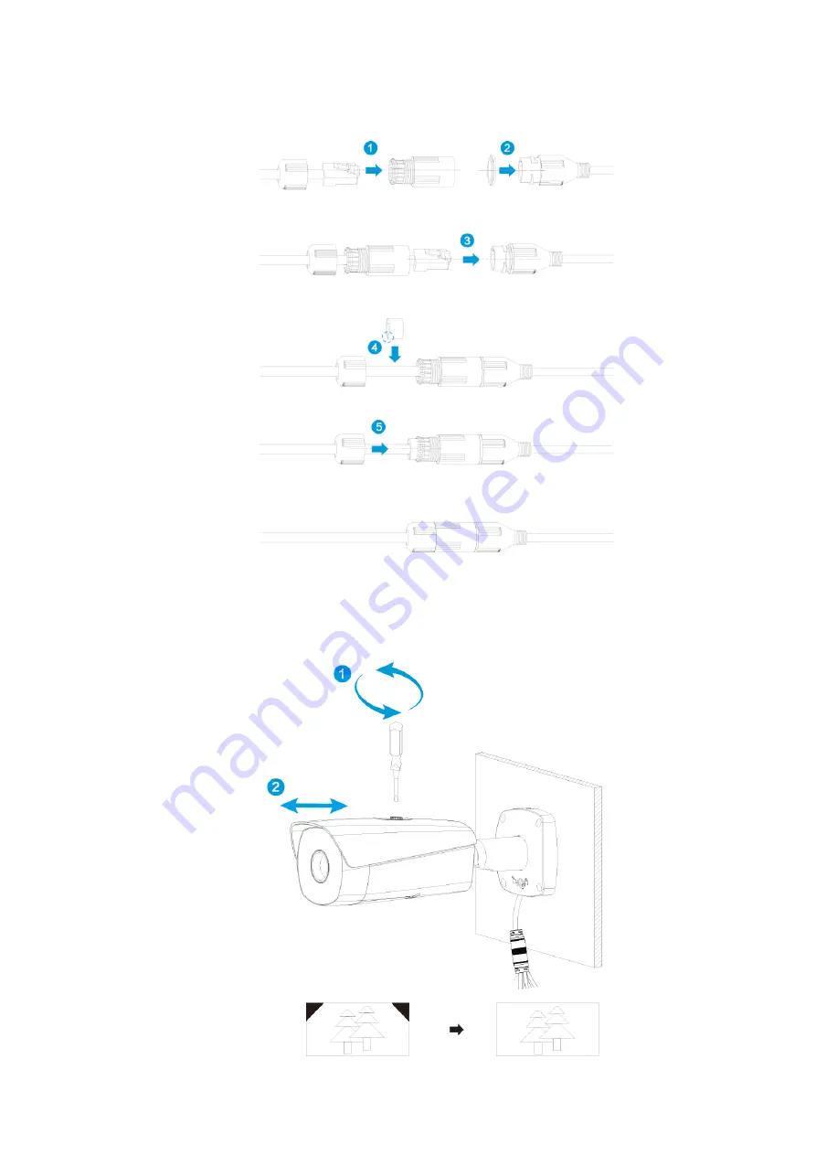
4.2.4 Installing Waterproof Connector
Installing waterproof connector for network port
Figure 4-3
4.2.5 Adjusting Sun Shield Cover
Adjusting sun shield cover
Figure 4-4
Page 1: ...Thermal Network Bullet Camera Quick Start Guide V1 0 0 ...
Page 2: ...guide may cause harmful interference to radio communication For class A device these limits are designed to provide reasonable protection against harmful interference in a commercial environment Operation of this equipment in a residential area is likely to cause harmful interference in which case the user will be required to correct the interference at his own expense For class B device these lim...
Page 3: ...n Revision Content Release Date 1 V1 0 0 First release January 21 2019 Privacy Protection Notice As the device user or data controller you might collect personal data of others such as face fingerprints car plate number Email address phone number GPS and so on You need to be in compliance with the local privacy protection laws and regulations to protect the legitimate rights and interests of other...
Page 4: ...ram and supplementary documentation There still might be deviation in technical data functions and operations description or errors in print If there is any doubt or dispute please refer to our final explanation Upgrade the reader software or try other mainstream reader software if the Guide in PDF format cannot be opened All trademarks registered trademarks and the company names in the Guide are ...
Page 5: ...e power supply is correct before operating the device Use power supply conforming to SELV requirements and power the camera in the rated voltage conforming to Limited Power Source in IEC60950 1 And refer to the camera label s power supply requirements for your final operation Please install easy to use device for power off before installing wiring which is for emergent power off when necessary Ple...
Page 6: ... dismantle the device there is no part which can be repaired by users themselves It may cause water leakage or bad image for the device if it is dismantled unprofessionally It is recommended to use the device together with a lightning arrester which is to improve the effect of lightning protection it needs to conform to the lightning protection regulation for outdoor application Do not touch the p...
Page 7: ...ntrol cabinet Please cut off power before device maintenance and overhaul It is prohibited to open the cover with power on in the explosion environment Please make sure all the explosionproof components and parts are complete without any cracks and there is no defect which may affect explosionproof performance Please contact the local dealer or the nearest service center if the device fails to wor...
Page 8: ...he system is equipped with the latest security patches and fixes When the equipment is connected to the public network it is recommended to enable the auto check for updates function to obtain timely information of firmware updates released by the manufacturer We suggest that you download and use the latest version of client software Nice to have recommendations to improve your equipment network s...
Page 9: ...ions to them 10 Disable Unnecessary Services and Choose Secure Modes If not needed it is recommended to turn off some services such as SNMP SMTP UPnP etc to reduce risks If necessary it is highly recommended that you use safe modes including but not limited to the following services SNMP Choose SNMP v3 and set up strong encryption passwords and authentication passwords SMTP Choose TLS to access ma...
Page 10: ...o the intranet devices from external network The network should be partitioned and isolated according to the actual network needs If there are no communication requirements between two sub networks it is suggested to use VLAN network GAP and other technologies to partition the network so as to achieve the network isolation effect Establish the 802 1x access authentication system to reduce the risk...
Page 11: ...ral Configuration 4 Initializing Camera 4 3 1 Modifying IP Address 5 3 2 Live Video 5 3 3 4 Installation 7 Cable Preparation 7 4 1 Installing Camera 8 4 2 4 2 1 Optional Installing SD Card 8 4 2 2 Fixing Camera 9 4 2 3 Connecting Cable Ports 9 4 2 4 Installing Waterproof Connector 10 4 2 5 Adjusting Sun Shield Cover 10 4 2 6 Adjusting Camera 11 5 Configuring Alarm 12 Lightening and Surge Protectio...
Page 12: ...Unpacking the Box 1 1 Unpacking the Box Refer to the following checklist and check the package If you find device damage or any loss contact the after sales service Checklist Figure 1 1 ...
Page 13: ...or more details about the cable function Table 2 1 Cable ports description SN Port Port Name Connector Function Description 1 AUDIO OUT Audio output port 3 5mm Jack port output audio signal to earphone and other devices 2 AUDIO IN Audio input port 3 5mm Jack port input audio signal receive analog audio signal from sound pick up and so on 3 LAN Network port Ethernet port Connect to standard Etherne...
Page 14: ...image Please refer to Table 2 2 for introduction of I O port function Table 2 2 I O port description Port Color Cable port name Function description I O port Green ALARM_COM1 Alarm output common port Use ALARM_COM1 together with ALARM_NO1 and use ALARM_COM2 together with ALARM_NO2 Pink ALARM_COM2 Blue ALARM_NO1 Alarm output port output alarm signal to alarm device NO Normally open alarm output por...
Page 15: ... by default and your PC s IP address are in the same network segment Open IE browser input camera default IP address in the address bar and then press Step 1 Enter The factory default IP address is 192 168 1 1087 The Device Initialization interface is displayed See Figure 3 1 Initializing camera Figure 3 1 Set the login password of admin See Table 3 1 for details Step 2 Table 3 1 Password descript...
Page 16: ...lect Setup Network TCP IP and the system will display the interface of TCP IP Step 2 which is shown in Figure 3 2 TCP IP Figure 3 2 Configure relevant info of IP address and click Save Step 3 Live Video 3 3 Different devices might have different WEB interfaces the figure in this document is just for reference please refer to the document WEB Operation Manual in the disk and the actual interface fo...
Page 17: ...u to install plug in for the first system login please save and install plug in according to prompt The web interface will refresh automatically after plug in installation is completed then live video will show up The live interface Figure 3 3 ...
Page 18: ...00Ft 457M Selecting Needed Power Cable It is recommended to implement according to the following requirements when the users need to lengthen the power cable Max Transmission distance is recommended when the size of wire diameter is fixed and DC 12V voltage transmission power is 10W Please refer to the following table for more details Table 4 2 Power cable Wire Diameter mm Max Distance Feet M 0 80...
Page 19: ... card slot for reset hole Long press the reset button for 4 seconds 5 seconds and you will reset your Camera Please check if the waterproof ring is installed properly before closing the cover otherwise it will affect the waterproof performance of the device Installing SD card Figure 4 1 Table 4 3 Camera component list No Name No Name 1 Micro SD card slot 2 Reset hole ...
Page 20: ... 4 2 2 Fixing Camera Fixing camera Figure 4 2 4 2 3 Connecting Cable Ports Refer to 2 2 Cable and connect each cable port to corresponding cables Then use the insulting tape to seal each port to prevent water leakage ...
Page 21: ...Installation 10 4 2 4 Installing Waterproof Connector Installing waterproof connector for network port Figure 4 3 4 2 5 Adjusting Sun Shield Cover Adjusting sun shield cover Figure 4 4 ...
Page 22: ... adjusting device direction and monitoring angle Tighten the adjusting screw firmly after adjustment is completed Please do not rotate the device body over 360 when the device body and mounting pedestal form an angle of 90 and the adjusting screw is firmly tightened Adjusting camera Figure 4 5 ...
Page 23: ...utput in the alarm setup interface Step 4 and then click Save See Figure 5 1 for the Alarm interface Alarm input is corresponding to the alarm input port of device I O cable It is to set corresponding NO and NC according to the high and low level signal generated by alarm input device when alarm occurs Alarm output is corresponding to the alarm output port of device I O cable The alarm interface F...
Page 24: ...g Alarm 13 Alarm output port ALARM_OUT and ALARM_COM form a switch which can be used to provide alarm output Normally the switch is on and the switch will be off when there is alarm output Alarm output Figure 5 3 ...
Page 25: ... the earth Open floor cable layout is forbidden In area of strong thunderstorm hit or near high sensitive voltage such as near high voltage transformer substation you need to install additional high power thunder protection device or lightning rod The thunder protection and earth of the outdoor device and cable shall be considered in the building whole thunder protection and conform to your local ...