Dahua DH-IPC-HFW5831EP-ZE Quick Start Manual Download Page 14


3


Network Configuration  

The IP address of all the cameras is the same when leaving factory (default IP 192.168.1.108). 

To make the camera access to the network smoothly, please plan the available IP segment 

reasonably according to the actual network environment.  

3.1


 Modify IP Address  

The cameras which are accessed via wired network can acquire and modify the IP address 

through "Quick Configuration Tool". This section introduces the approach of modifying IP address 

via "Quick Configuration Tool". You can also modify the IP address in the network parameters of 

the WEB interface. Please refer to the document 

WEB Operation Manual 

in the disk for more 

details.  

To modify IP address, do the following: 

Step 1 

Double-click "ConfigTool.exe" to open the "Quick Configuration Tool".  

Step 2 

Click

 to enter the interface where you can modify IP address, and then click 

Search 

setting

.  

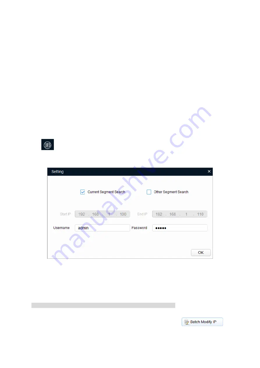
The system pops up the 

Setting

 dialog box, see Figure 3-1. 


Figure 3-1 

Step 3 

Set the device network segment, login user name and password, and then click 

OK

. The system 

will display the searched devices after searching completes.  

Note  

The default username and password is 

admin

 and 

admin

 respectively.  

Step 4 

Select the devices which IP addresses need to be modified, and then click

.  

The system will pop up the 

Modify IP


Address

 dialog box, see Figure 3-2.  

Summary of Contents for DH-IPC-HFW5831EP-ZE

Page 1: ...Dahua HD IR Network Dome Camera Quick Start Guide Dahua HD IR Bullet Network Camera Quick Start Guide Version 1 0 2 ZHEJIANG DAHUA VISION TECHNOLOGY CO LTD...

Page 2: ...e same time it may result in device damage We assume no liability or responsibility for all the fires or electrical shock caused by improper handling or installation We are not liable for any problems...

Page 3: ...he surface coating or reduce the working performance of the device Dome cover is an optical device please don t touch or wipe cover surface directly during installation and use please refer to the fol...

Page 4: ...ce This equipment generates uses and can radiate radio frequency energy and if not installed and used in accordance with the instruction manual may cause harmful interference to radio communication Ho...

Page 5: ...of Contents 1 Device Structure 1 1 1 Device External Cable 1 1 2 Framework and Dimension 2 1 3 Alarm Setup 3 2 Device Installation 5 3 Network Configuration 9 3 1 Modify IP Address 9 3 2 Login WEB Int...

Page 6: ...following figure for cable information See Figure 1 1 Figure 1 1 Please refer to Table 1 1 for detailed information No Port Name Function Connector Function Description 1 AUDIO OUT Audio output port R...

Page 7: ...Name Function description I O Port 1 ALARM_NO Alarm output port It is to output the alarm signal to the alarm device NO normal open alarm output port It must be used with ALARM_COM 2 ALARM_COM Alarm o...

Page 8: ...orresponding to that of the device I O port cable When there is alarm alarm input device will generate signal of high and low level Set corresponding NO and NC inputs Step 4 Set alarm output on the WE...

Page 9: ...nally to work normally Max external pull up level is 12V max port current is 300mA peak After external pull up resistance is increased the default output signal is high level external pull up voltage...

Page 10: ...ion Optional Note It needs to implement the step when the device is equipped with Micro SD card slot and it needs to use Micro SD card 1 Loosen the screw on the lower cover You can see the Micro SD ca...

Page 11: ...g take out expansion bolt and insert it into the hole you just dug lock it firmly 3 Open the accessories bag take out installation screws Align the screw hole of the device bottom with the mounting ho...

Page 12: ...tate it clockwise to lock the network port and waterproof connector firmly 4 Put the waterproof locking cover on the main body of waterproof connector and rotate it clockwise to lock the waterproof co...

Page 13: ...2 4 1 Use screwdriver to loosen adjusting screw 2 Adjust the device in all possible directions and set its monitoring direction according to use requirement 3 Use screwdriver to tighten the adjusting...

Page 14: ...of the WEB interface Please refer to the document WEB Operation Manual in the disk for more details To modify IP address do the following Step 1 Double click ConfigTool exe to open the Quick Configura...

Page 15: ...to finish modification 3 2 Login WEB Interface Note Different devices might have different WEB interfaces the figures in this document are just for reference please refer to the document WEB Operatio...

Page 16: ...The default username and password is admin and admin respectively please modify the administrator password as soon as possible after you successfully logged in Step 3 Click Here to Download Plug in a...

Page 17: ...tice If there is any uncertainty or controversy please refer to the final explanation of us Please visit our website or contact your local service engineer for more information Dahua Vision Technology...

Reviews: