background image


2  Device Installation 

2.1  Install Device 

Note 


The follow installation figures are for reference only, please refer to the actual product for 

more details.


Lens assembly mode may be different according to different devices, please refer to the 

actual lens for more details.


The bracket mounting wall needs to sustain at least 3X weight of camera and bracket.


The device is not quipped with bracket by default, you needs to purchase separately if 

necessary.


Install Lens 


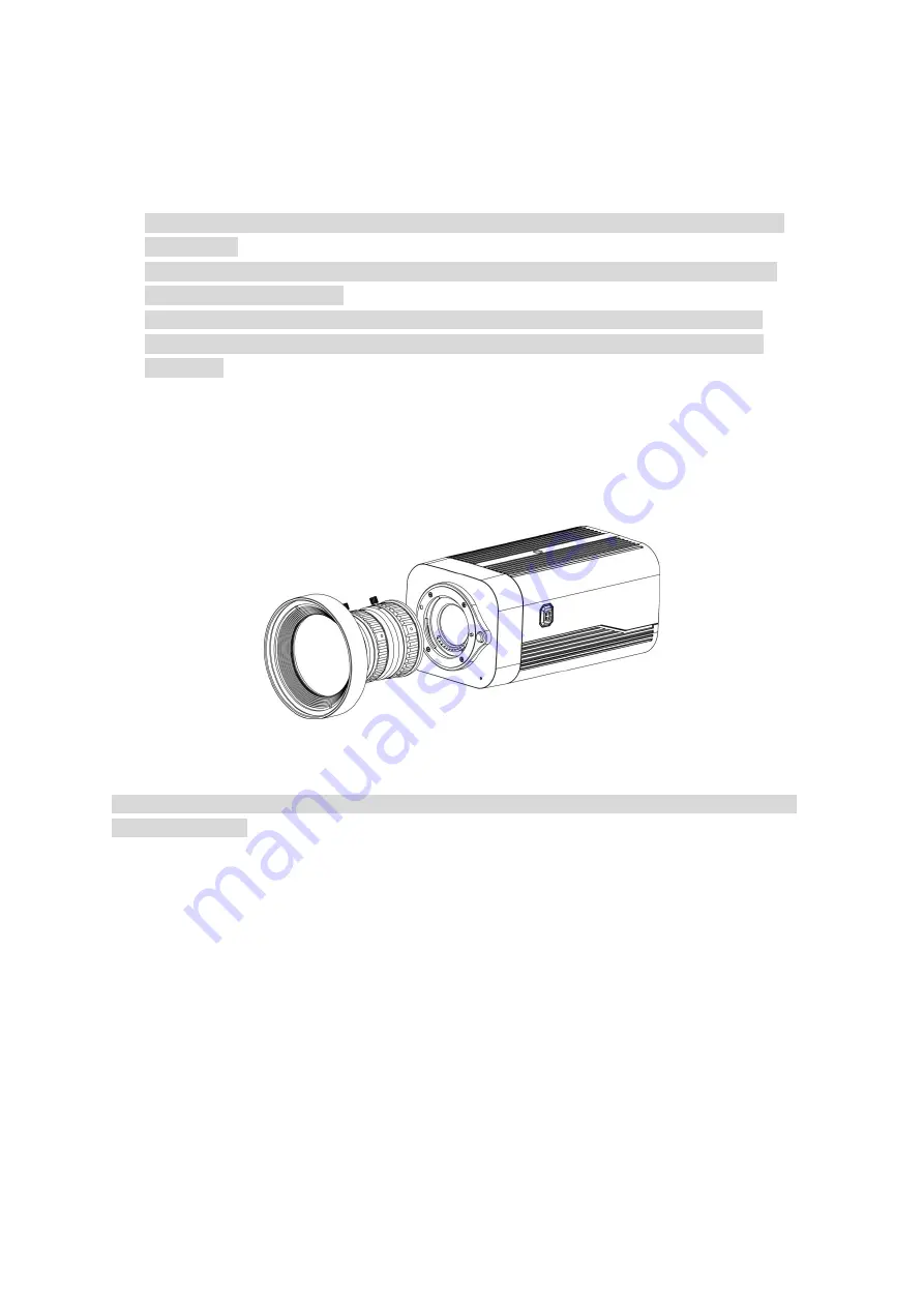
When the device lens mount is bayonet, it supports installing the lens which conforms to 

bayonet. 

Dismantle the protection cover on the device, align the red spot on the lens with the red spot 

of the lens mount, and rotate the lens clockwise till it is secured and installed properly. 


Figure 2-1 

Note 

First press the button on the upper side of lens mount, and then rotate the lens anticlockwise to 

dismantle the lens. 


When the lens mount is screw-threaded, different types of lens have different installation 

modes; please select according to the actual situation. 

Summary of Contents for DH-IPC-HF8242FP-FR

Page 1: ...Dahua HD Box Network Camera Quick Start Guide Version 1 0 0 Zhejiang Dahua Vision Technology Co LTD...

Page 2: ...r installation Environment Do not aim the device at strong light to focus such as lamp light and sun light otherwise it might cause over brightness or light marks which are not the device malfunction...

Page 3: ...gerprint use soft cloth to gently wipe the water drop or oil and wait till it is dry and then use oil free cotton cloth or lens cleaning paper soaked with alcohol or detergent to wipe from the lens ce...

Page 4: ...s This device complies with part 15 of the FCC Rules Operation is subject to the following two conditions This device may not cause harmful interference This device must accept any interference receiv...

Page 5: ...s manual and tool Before installation please open the package and check all the components are included Contact your local retailer as soon as possible if something is broken in your package Accessor...

Page 6: ...2 Dimension 4 2 Device Installation 6 2 1 Install Device 6 2 2 Connect Device Cable 8 2 3 Connect Alarm Input Output Port 8 2 4 Adjust Device Angle 10 3 Network Configuration 11 3 1 Device Initializa...

Page 7: ...el Note The figures are for reference only which are used to know the functions of the rear panel Different devices may have different structures of rear panel please refer to the actual product for m...

Page 8: ...onitor to preview image AC 24V DC 12V Power port Able to input 12V DC or AC 24V power supply and support power supply at the same time Indicator Light Red light System boots up red light is normally o...

Page 9: ...larm device C1 N2 C2 P Power foldback output port It outputs DC 12V power P connects to positive pole while G connects to negative pole G adjacent to P RESET RESET button Restore device factory defaul...

Page 10: ...function OPT Transmit MB Ethernet data SD SD card port Connect it to SD card GND Please make sure the device is securely earthed to prevent the thunderstorm strike when using the device Table 1 1 1 2...

Page 11: ...5 Figure 1 5...

Page 12: ...eeds to purchase separately if necessary Install Lens When the device lens mount is bayonet it supports installing the lens which conforms to bayonet Dismantle the protection cover on the device align...

Page 13: ...ing ring on the device Only type C lens needs to install adapter ring 3 Align C mount lens with the lens mounting location of C CS adapter ring CS mount lens aims at the lens mounting location on the...

Page 14: ...being damaged Step 3 Align the screw holes of bracket bottom with the mounting hole sites of mounting surface use self tapping screws to fix the bracket on the mounting surface Step 4 Align the mount...

Page 15: ...of I O port cable N1 and C1 or N2 and C2 make up a switch to provide the alarm output which is shown in Figure 2 5 Generally the switch is on and it will be off when there is an alarm output Figure 2...

Page 16: ...e corresponding button of cable groove Step 2 Insert the cable into the groove Step 3 Release the screwdriver which presses the groove button and complete cable installation 2 4 Adjust Device Angle St...

Page 17: ...rder to make the camera have access to network smoothly please plan available IP segment according to the actual network environment The following figures are for reference only different models may h...

Page 18: ...on the system begins to initialize the device means initialization succeeded means initialization failed Click the icon to check more details Step 7 Click OK to complete device initialization 3 2 Modi...

Page 19: ...om the DHCP server Step 6 Click OK to complete modification of device IP address 3 3 Login WEB Interface Step 1 Open IE browser enter the modified camera IP address into the address bar and then press...

Page 20: ...Zhejiang Dahua Vision Technology Co Ltd Address No 1199 Bin an Road Binjiang District Hangzhou PRC Postcode 310053 Tel 86 571 87688883 Fax 86 571 87688815 Email overseas dahuatech com Website www dahu...

Reviews: