Dahua DH-HAC-HDBW2231F User Manual Download Page 11


Step 1  

Take out the installation position map from the accessories bag, and paste it on the ceiling or 

wall 

 according to the cable outlet location, dig holes on the installation surface according to 

the installation position map, take out the expansion bolts 

 from the accessories bag and 

insert them into the installation holes and fix them.  

Step 2  

Use inner hex wrench 

 to loosen three locking screws 

 in the enclosure and take down the 

enclosure 

.  

Step 3  

Adjust the location of the dome pedestal 

 according to the top cable outlet or side cable 

outlet. Pull the cable out through the side outlet of installation surface and pedestal (please 

skip the step if it is top cable outlet), aim the screw fixing holes of dome pedestal to the fixing 

holes of expansion boles on the installation surface, then insert the self-tapping screws 

 into 

the expansion bolts and secure them firmly, fix the dome on the installation surface.  

Step 4  

Connect the video output port of the device to the back-end encoding device and connect the 

power port to power.  
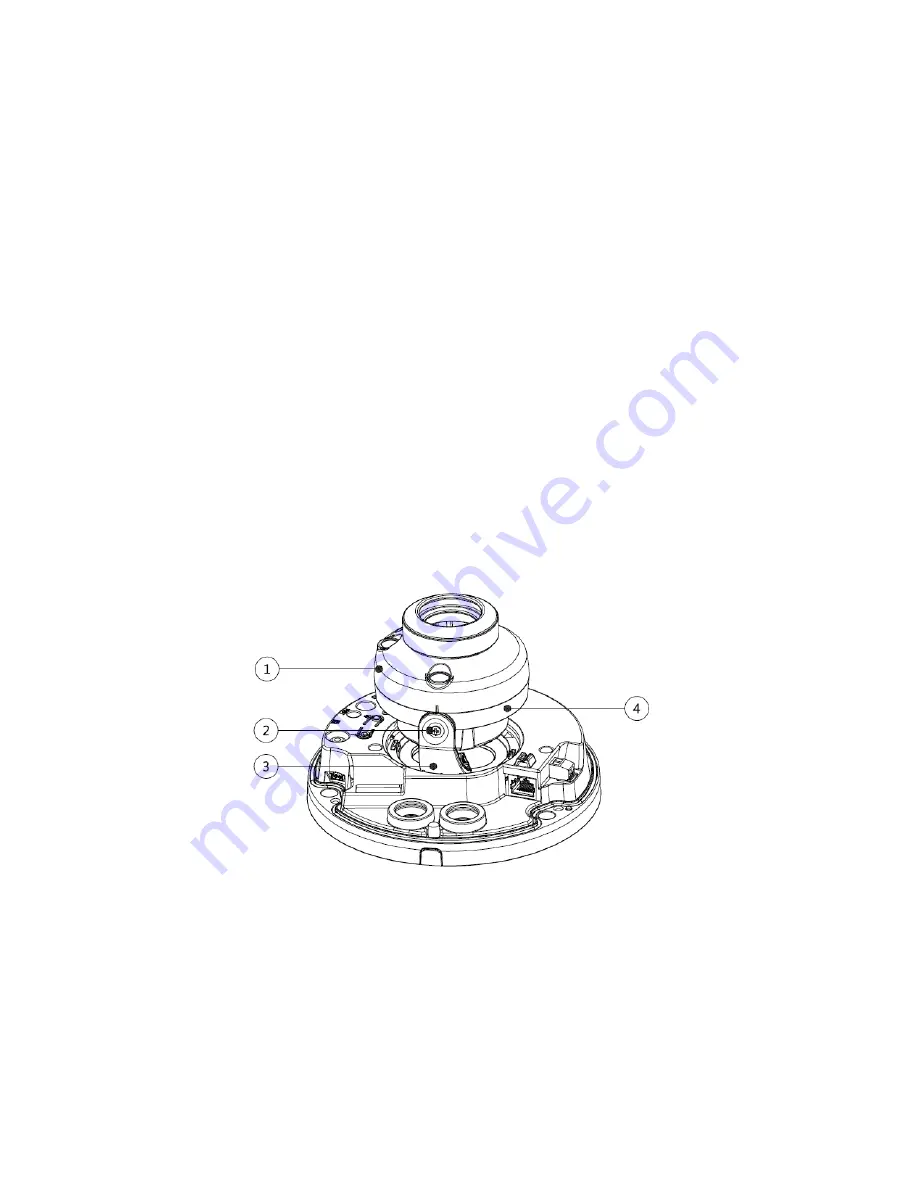
Step 5  

Adjust the lens angle to proper monitoring location after the image displays on the back-end 

encoding device, and then adjust focal length of the lens to make image clear, which is shown 

in Figure 4-2.  


Figure 4-2 

It can realize coaxial control via five-direction button for model A, which is shown in Figure 4-3.  


Long press the middle button for 5 seconds to realize HD/SD switch.  


Short press the middle button to enter OSD menu, short press the middle button again to 

confirm after entering OSD menu, up and down buttons are used to select menu options, 

left and right buttons are used to adjust parameter value.  


When the OSD menu is not enabled, you can adjust zoom via up and down buttons, 

adjust focus via left and right buttons.  

Summary of Contents for DH-HAC-HDBW2231F

Page 1: ...HDCVI Camera User s Manual Version 1 0 0 ...

Page 2: ...1 Overview 1 1 2 Features 1 2 Device Framework 2 3 Device Cable Structure 4 4 Device Installation 6 4 1 Installation for Model A B and D 6 4 2 Installation for Model C 8 5 Menu 10 5 1 HCVR Settings 10 5 2 Menu Operation 10 Appendix Ⅰ Maintenance 12 ...

Page 3: ... the plug power socket and the junction from the device 2 Environment Please don t aim the device at strong light such as lighting sunlight and so on to focus Please transport use and store the device within the range of allowed humidity and temperature Please do not allow water and other liquid falling into the camera in case that the internal components are damaged Please keep the sound ventilat...

Page 4: ... manual will be regularly upgraded according to the product update the upgraded content will be added in the manual without prior announcement Please contact the customer service for the latest procedure and supplementary documentation The company is not liable for any loss caused by the operation which is not followed by the manual Please refer to the company s final explanation if there is any d...

Page 5: ...hout any loss The distance is over 500m High speed long distance real time transmission Support HDCVI HD video and CVBS analog SD video output Support 3D noise reduction some models support 2D noise reduction excellent low illuminance performance Support ICR switch to realize surveillance both in the daytime and at night Support OSD menu adjustment parameters Support smart IR function Support WDR ...

Page 6: ...and C it realizes zoom and focus operation via UTC when it outputs SD video for model A and D See Figure 2 1 for the dimension of model A The unit is mm Figure 2 1 See Figure 2 2 for the dimension of model B The unit is mm Figure 2 2 See Figure 2 3 for the dimension of model C The unit is mm Figure 2 3 ...

Page 7: ...3 See Figure 2 4 for the dimension of model D The unit is mm Figure 2 4 ...

Page 8: ...re 3 3 for video output port Figure 3 3 Note Video output port yellow analog video output port Video output port black HDCVI HD video output port Some models only have one black video output port HD SD output can be switched via PFM820 UTC Controller or OSD menu Advanced Video Output Video output port red SDI port Refer to Figure 3 4 for audio input port Figure 3 4 ...

Page 9: ...ion of alarm cable Sheet 3 1 Color Port Function Red ALARM_IN Alarm input port it is to receive the signal of external alarm Black ALARM_GND Alarm GND Orange ALARM_NC Alarm output common contact on off value alarm output Green ALARM_NO Alarm output normally open contact on off value alarm output ...

Page 10: ...For the installation mode of side outlet make sure the direction of side outlet is in accordance with that of the installation position map when sticking the installation position map Besides pull the cable through the pedestal cable slot before locking the screw Please don t tear off the electrostatic adsorption film on the surface of transparent cover before installation debugging is completed w...

Page 11: ...surface then insert the self tapping screws into the expansion bolts and secure them firmly fix the dome on the installation surface Step 4 Connect the video output port of the device to the back end encoding device and connect the power port to power Step 5 Adjust the lens angle to proper monitoring location after the image displays on the back end encoding device and then adjust focal length of ...

Page 12: ...ws in the enclosure to fix the dome enclosure on the dome pedestal So far the device installation and cable connection have been completed you can check the monitoring image via back end encoding device 4 2 Installation for Model C Figure 4 4 ...

Page 13: ... the step if it is top cable outlet aim the screw fixing holes of dome pedestal to the fixing holes of expansion boles on the installation surface then insert the self tapping screws into the expansion bolts and secure them firmly fix the dome on the installation surface Step 4 Connect the video output port of the device to the back end encoding device and connect the power port to power Step 5 Ad...

Page 14: ...nu Setting System PTZ you need to select the channel number for access and set control mode as HDCVI and the protocol as HD CVI Click Save button to save current setup See Figure 5 1 Figure 5 1 5 2 Menu Operation Click the right mouse button and select PTZ Control then you will see the PTZ Setup menu which is as shown in Figure 5 2 and Figure 5 3 Figure 5 2 ...

Page 15: ...ens zoom and auto trigger focus Note Some of the buttons can only be applied for the motorized vari focal camera Adjust lens focus Auto focus under current zoom rate Lens reset Sheet 5 1 If there is click the Confirm button in Menu Operation interface to go to the 2nd menu Click Return button to go back to the previous menu interface ...

Page 16: ...cloth and wipe several times if it is not clean enough Camera Body Maintenance Use a soft dry cloth to clean the camera body when it is dirty in case the dirt is hard to remove use a clean dry cloth soaked with mild detergent and wipe gently make it dry later Don t use volatile solvent like alcohol benzene thinner and etc or strong detergent with abrasiveness otherwise it will damage the surface c...

Page 17: ... here are subject to change without prior written notice All trademarks and registered trademarks mentioned are the properties of their respective owners If there is any uncertainty or controversy please refer to the final explanation of us Please visit our website or contact your local service engineer for more information ...

Reviews: