background image


25 

that belong to the same aggregation group can be considered as a logical link with bigger 
bandwidth. 
Link aggregation can realize sharing responsibility of communication flow among each member 
port in the aggregation group, which is to increase bandwidth. Meanwhile, mutual dynamic backup 
can be realized among each member port in the same aggregation group, which is to improve the 
link reliability. 
There must be certain configurations for member ports which belong to the same aggregation 
group. These configurations include STP, QoS, VLAN, port properties, MAC address study, mirroring, 
802.1x and MAC filtering. 


  The link aggregation is mutually exclusive with STP mode. When STP mode is enabled, link 

aggregation cannot be configured. You must disable STP mode before configuring link 
aggregation. 

  We do not recommend implementing configuration and advanced functions for the ports which 

are used for link aggregation. 

  Link aggregation can be divided into static aggregation and LACP. Generally, the peer devices 

with the switch link aggregation are switch and network adapter. 

  Only the ports with the same speed rate, duplex, long distance and VLAN configuration can be in 

the one aggregation group. 

5.3.1 Static Aggregation Mode 

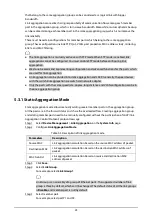
Static aggregation mode allows manually adding several member ports in the aggregation group. 
All the ports are in the forward status and share the overloaded flow. Creating aggregation group 
and adding member ports need to be manually configured without the participation of LACP (link 
Aggregation Control Protocol) protocol message. 
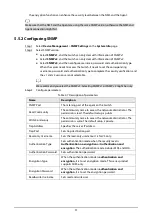
Step 1 

Select 

Device Management

 > 

Link Aggregation

 on the 

System Info

 page. 

Step 2 

Configure 

Link Aggregation Mode

Table 4-5 Description of link aggregation mode. 

Parameters 

Description 

Source MAC 

Link aggregation calculation based on the source MAC address of packet. 

Destination MAC 

Link aggregation calculation based on the destination MAC address of 

packet. 

MAC Src&Dst 

Link aggregation calculation based on source and destination MAC 

address of packet. 

Step 3 

Click 

Save

Step 4 

Select 

Link Group

For example, select 

Link Group 1


Link Group is an assembly of a group of Ethernet ports. The supported number of link 
group is three by default, which can't be changed. The default status of all the link groups 
is 

Disable

, and member port is null by default. 

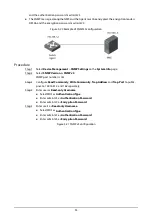
Step 5 

Select member port. 
For example, select port P1 and P2. 

Summary of Contents for D-PFS4226-24ET-240

Page 1: ...PoE Switch 16 24 Port Managed Desktop Switch Web Operation Manual V1 0 1...

Page 2: ...ata loss reductions in performance or unpredictable results Provides methods to help you solve a problem or save time Provides additional information as a supplement to the text Revision History Versi...

Page 3: ...e the paper user s manual use our CD ROM scan the QR code or visit our official website The manual is for reference only Slight differences might be found between the electronic version and the paper...

Page 4: ...trictly abide by local electrical safety standards and make sure that the voltage in the area is steady and conforms to the power requirements of the device Do not connect the device to more than one...

Page 5: ...hen installing the device make sure the power plug and appliance coupler are easy to reach to cut off the power Maintenance Requirements When replacing the battery make sure that the same type is used...

Page 6: ...Information 7 3 8 Viewing Legal Information 8 4 Port Management 9 4 1 Configuring Port 9 4 2 Configuring Port Mirroring 10 4 3 Configuring Port Statistics 11 4 4 Configuring Port Speed Limit 12 4 5 Co...

Page 7: ...SNMPv3 Configuration 32 5 6 802 1x 34 5 6 1 802 1x Networking Structure 34 5 6 2 802 1x Authentication Controlled Uncontrolled Port 35 5 6 3 Trigger Mode of 802 1x Authentication 35 5 6 4 Configuring...

Page 8: ...ress bar and press the Enter key Step 2 Enter the username and password and then click Login The username and the password are admin and admin123 by default Change the password after the first login T...

Page 9: ...the Switch System Info Configure the Switch by accessing System Config Port Management Device Management and PoE Logout Return to the login page 2 Panel status graph Switch port is green Successfully...

Page 10: ...usage Select System Config System Info and then you will see the options in the menu Figure 2 1 System configuration 3 1 1 Viewing System Information You can view information on the Switch model MAC...

Page 11: ...3 Current time 3 1 3 Viewing CPU Usage Step 1 Select System Config System Info CPU Usage on the System Info page Step 2 View the CPU usage of the Switch Figure 2 4 CPU usage 3 2 Configuring Network Th...

Page 12: ...atically obtain a dynamic IP address saving you from configuring the IP address and other information IP address When the mode is set to Static enter the IP address subnet mask and default gateway acc...

Page 13: ...Confirm Password Figure 2 7 Modify password Step 3 Click Save 3 5 Restoring to Default You can restore the Switch to its default settings There are two methods to restore the Switch to its default set...

Page 14: ...e lost You need to log in to the web page again after the Switch restarts Step 1 Select System Config System Reboot on the System Info page Step 2 Click Manual Reboot Figure 2 9 Restart system 3 7 Log...

Page 15: ...ion 3 8 Viewing Legal Information You can view the software license agreement privacy policy and open source software notice Step 1 Select System Config Legal Info on the System Info page Step 2 View...

Page 16: ...equirements Step 1 Select Port Management Port Configuration on the System Info page Figure 3 1 Configure port Step 2 Configure port parameters Table 3 1 Description of parameters Parameter Descriptio...

Page 17: ...ol On Enable port flow control function Off Disable port flow control function For Ethernet port you need to enable port flow control function to synchronize the inbound speed and the outbound speed t...

Page 18: ...setup is disabled Src port The port that is being monitored Select one or more port s Enable Enable the function on the selected ports Step 3 Click Save 4 3 Configuring Port Statistics You can view p...

Page 19: ...or packets from the port the working status of the port is very poor Make sure to check if there is a problem with the cable connected to the port or the Switch Related Operations Clear statistic resu...

Page 20: ...imit Step 3 Click Save 4 5 Configuring Broadcast Storm Control Background Information The broadcast frames on the network are forwarded continuously which affects the proper communications and greatly...

Page 21: ...properly transmit the data Figure 3 5 Configure broadcast storm control Step 4 Click Save 4 6 Long Distance Transmission You can set port long distance transmission mode For the standard Ethernet mode...

Page 22: ...ata between the ports in the isolation group The port isolation function provides users a safer and more flexible networking solution Step 1 Select Port Management Port Isolation on the System Info pa...

Page 23: ...16 Figure 3 7 Configure port isolation Step 4 Select checkbox under Enable to select one or more ports to be isolated Step 5 Click Save below the port list...

Page 24: ...ed for spanning tree calculation Figure 4 1 Frame format and field description of STP Protocol Identifier The identification of protocol Version The protocol version Message Type BPDU type Flag Flag b...

Page 25: ...ggregation STP mode cannot be enabled Bridge Priority Set bridge priority The value ranges from 0 to 61440 Hello Time Set the period of root bridge sending BPDU The time ranges from 1 s to 10 s Max Ag...

Page 26: ...LAN VLAN A VLAN is divided from a LAN on a logical basis rather than on a physical basis to realize the isolated broadcast area in the VLAN 5 2 2 VLAN Function Enhance the network performance The bro...

Page 27: ...gs to one VLAN and is used to connect to the computer port Trunk The port allows multiple VLANs to pass to receive and send messages of multiple VLANs and is used to connect between the switches Hybri...

Page 28: ...the accepted list remove the tag and send out the message When the VLAN ID is different from the default VLAN ID and it is on the accepted list keep the tag and send out the message Hybrid When VLAN...

Page 29: ...ring VLAN related to port the added VLAN member can be displayed Modify VLAN Select VLAN that has been added in the list and then click to modify VLAN ID and Description Delete VLAN Select VLAN that h...

Page 30: ...ult The range is from 1 through 4094 Egress Tagging Configure the Egress tag type Access port No need to configure Trunk port Untag Port VLAN Indicates that if the data steam tag is the same as the PV...

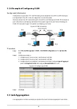
Page 31: ...rt 1 of switch B and it belongs to VLAN2 Figure 4 9 VLAN networking Procedure Step 1 Select Device Management VLAN Port VLAN Configuration on the System Info page Step 2 Configure parameters 1 Configu...

Page 32: ...rts with the same speed rate duplex long distance and VLAN configuration can be in the one aggregation group 5 3 1 Static Aggregation Mode Static aggregation mode allows manually adding several member...

Page 33: ...ll dominate convergence and convergence separation and the Switch priority is decided by system priority and system MAC The Switch with lower system priority value has higher priority And the Switch w...

Page 34: ...en two devices are interconnected at least one or both ends need to be set as Active the mode can be successfully negotiated Procedure Step 1 Select Device Management Link Aggregation on the System In...

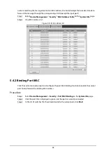
Page 35: ...address list Figure 4 13 MAC address list 5 4 2 Binding Port MAC Click the current connected port and configure the port MAC binding function to enable the current port to only forward the binding MAC...

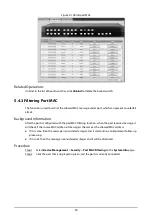
Page 36: ...port MAC filtering function when the port receives message it will check if the source MAC address of message is the same as the allowed MAC address If it is same then the message is considered as leg...

Page 37: ...certify The community name is like a password to restrict the communication between the NMS and Agent If the NMS community name and the managed Switch community name are not the same then the NMS and...

Page 38: ...ameters Table 4 7 Description of parameters Name Description SNMP Port The listening port of the agent on the Switch Read Community The community name to access the network administrator The permissio...

Page 39: ...2 Select SNMP Version to SNMP v2 and then set the SNMP port number to 161 Step 3 Configure Read Community Write Community Trap Address and Trap Port to public private 192 168 1 2 and 162 separately F...

Page 40: ...SNMP Version as SNMP v3 SNMP port number is 161 Step 3 Configure Read Community Write Community Trap Address and Trap Port to public private 192 168 1 2 and 162 separately Step 4 Enter user as Read o...

Page 41: ...ion function must be configured on the device port and for the user device which is accessed through the port can have control on the access on network source through authentication 5 6 1 802 1x Netwo...

Page 42: ...ransmit authentication messages and make sure that the Client can always send or receive authentication messages The controlled port is always in the status of bidirectional connection in the authoriz...

Page 43: ...S By configuring the authorization status of the port you can control whether users connected to the port need to be authenticated to access network resources Step 1 Select Device Management 802 1X NA...

Page 44: ...es not provide authentication services for clients that access through this port Port based 802 1X Indicates that the initial state of the port is an unauthorized state and users are not allowed to ac...

Page 45: ...forwarding of multicast data message and realize required distribution on layer two of multicast data packet 5 7 1 IGMP Snooping Theory Operating layer two device of IGMP Snooping can establish mappi...

Page 46: ...ide Web server and how the server transmits the document to the browser From a hierarchical point of view HTTP is a transaction oriented application layer protocol which is an important basis for reli...

Page 47: ...TTPS from Device Management HTTPS on the System Info page Step 2 Select HTTPS and then click Save Figure 4 27 HTTPS Step 3 Select Certificate Management and then click Create Server Figure 4 28 Certif...

Page 48: ...he creation is successful the prompt Create Succeed displays Figure 4 30 Create Server 2 Step 7 Click Download Root Step 8 Open the downloaded root certificate file and then click Run on the Security...

Page 49: ...ck Install Certificate Figure 4 32 Certificate Step 10 Click Next Figure 4 33 Certificate import wizard Step 11 Select Automatically select the certificate store base on the type of certificate and th...

Page 50: ...43 Figure 4 34 Store certificate Step 12 Click Finish Figure 4 35 Complete the certificate import wizard...

Page 51: ...ies power to the whole system PSE Directly supplies power to the PD Supports searching detecting PD categorizing PD realizing power consumption management and checking the PD connection PI The Etherne...

Page 52: ...E Settings Step 2 Configure parameters Figure 5 2 Configure PoE Table 5 2 Description of parameters Parameters Description Power Setting Total Power Displays the total PoE power Available Power Config...

Page 53: ...PD When selecting the Enable the PoE port will not result in PoE power overload Otherwise you are not allowed to enable PoE for the PoE port By default PoE is disabled on a PoE port PSE power overloa...

Page 54: ...cuit when the powering chip sends out power Thermal Shutdown The powering chip temperature is too high resulting from short circuit or other reasons 6 3 Configuring Green PoE You can set PoE Off Time...

Page 55: ...page Step 2 Select port that needs to enable the Legacy Support function Figure 5 5 Configure Legacy Support Step 3 Click Save 6 5 Configuring PD Alive When the Switch detects that the camera has no d...

Page 56: ...49 Figure 5 6 Configure PD alive Step 3 Click Save...

Page 57: ...om and cabinet and implement well done access control permission and key management to prevent unauthorized personnel from carrying out physical contacts such as damaging hardware unauthorized connect...

Page 58: ...we suggest that you check online users regularly to see if the device is logged in without authorization Check equipment log By viewing the logs you can know the IP addresses that were used to log in...

Reviews: