7
Indicators are defined as:
No.
Note
15
Lock status indicator
16
17
18
19
Power indicator
4.2 Cabling
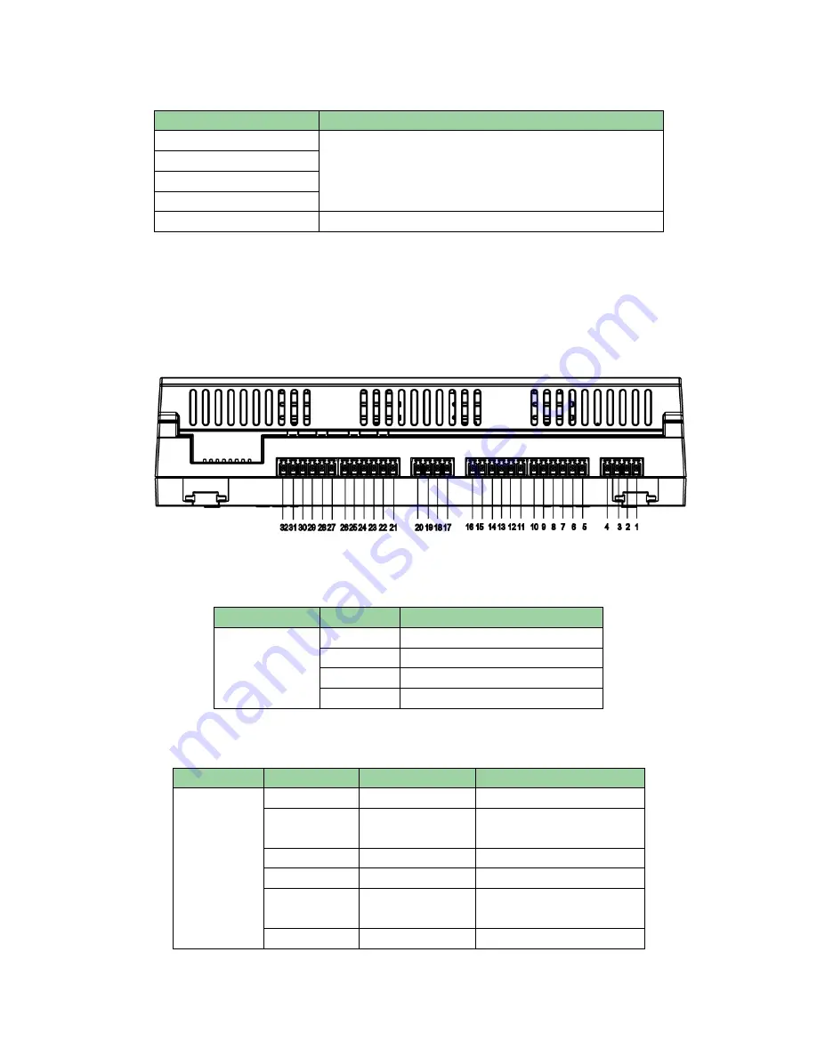
Cabling ports of No.1 to 7 are shown as Figure 4- 2.
Figure 4- 2
Cabling ports of “RS485 communication” are as follows:
Port
No.
Cabling Port
485
Communication
1
GND
2
GND
3
485-
4
485+
Cabling ports of “Door sensor” are as follows:
Port
No.
Cabling Port
Note
Door
Sensor
5
PUSH1
No.1 door’s unlock button
6
GND
No.1 door’s unlock button
and door sensor
7
SR1
No.1 door’s door sensor
8
PUSH2
No.2 door’s unlock button
9
GND
No.2 door’s unlock button
and door sensor
10
SR2
No.2 door’s door sensor


