background image


5.9


Protocol  

Warning 

After you add or delete protocol, you must reboot the device to make adding/deleting 

valid.  


Add relative peripheral protocol, to link video field surveillance unit and peripheral.  


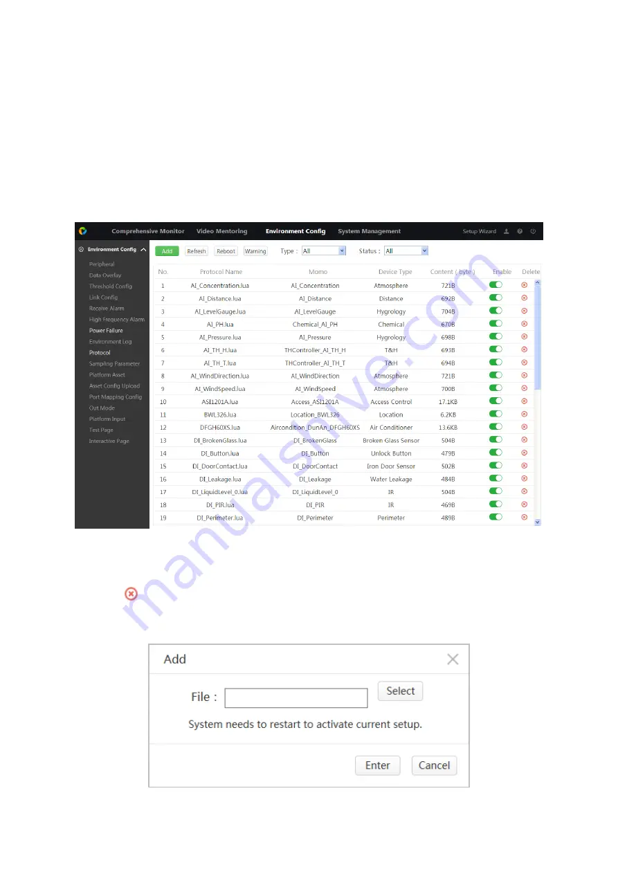
Step 1. Select Environment Config>Protocol, see Figure 5-17. 


Figure 5-17 


Click Warning, to enable/disable warning delay.  


Click 

 to delete this protocol.  


Step 2. Click Add. See Figure 5-18. 


Figure 5-18 

Summary of Contents for ARC6416C series

Page 1: ...1 Video Field Surveillance Unit User s Manual V 1 0 0 For ARC6416C series...

Page 2: ...Position 6 3 1 2 Common Tool 6 3 1 3 Requirements for Installation 6 3 2 Install Field Surveillance Unit 7 3 3 Install Peripherals 7 3 4 Wiring 7 3 4 1 Main Power Wiring 7 3 4 2 Network Port Wring 7 3...

Page 3: ...Connection 21 4 3 7 Platform Input 22 4 3 8 Delivery Mode 23 5 ENVIRONMENT CONFIGURATION 24 5 1 Peripheral 24 5 2 Data Overlay 27 5 3 Threshold Config 28 5 4 Link Config 30 5 5 Receive Alarm 32 5 6 H...

Page 4: ...8 Email 59 6 2 9 FTP 60 6 2 10 SNMP 62 6 2 11 Multicast 63 6 2 12 VPN 64 6 2 13 Alarm Center 66 6 2 14 P2P 67 6 2 15 HTTPS 68 6 3 Event 73 6 3 1 Video Detect 73 6 3 2 Alarm 78 6 3 3 Abnormality 79 6...

Page 5: ...7 2 Add Peripheral 98 7 3 View Peripheral Status 98 8 LIVE 100 8 1 Live 100 8 2 Live 100 8 3 Audio Talk 101 8 4 Instant Record 102 8 5 Local Play 102 8 6 Window Display Mode 102 8 7 PTZ 103 8 7 1 PTZ...

Page 6: ...r quilt Do not block air vent of the device or ventilation around the device Otherwise temperature in device will rise and may cause fire Do not place any object on the device Do not disassemble the d...

Page 7: ...smart residence factory and other fields 1 2 Features Environment Value Collection Support 4mA 20mA or 0V 5V analog value data collection RS485 RS232 BUS environment value data collection Environment...

Page 8: ...Figure 1 1...

Page 9: ...32 6UNC screw Right hanger Terminal Quick start guide Cable Warranty card Chart 2 1 2 2 Dimensions Device dimensions is 440mm 312mm 42mm L W H see Figure 2 1 Figure 2 1 2 3 Front Panel Front panel inc...

Page 10: ...arm occurs HDD indicator Blue HDD is normal OFF HDD is abnormal or capacity warning it generates alarm Network indicator Blue network is normal OFF network is abnormal or not connected it generates al...

Page 11: ...serial 14 Audio input port 4 Smoke sensor port 15 Battery port 5 RS485 16 Siren port 6 RS232 17 Peripheral power port 7 DI port 18 Alternate power port DC8 48V 8 AI port 19 Main power port DC12V 9 DO...

Page 12: ...of device bottom from the installation ground is 1 4 meters or the installation height flushes with the AC distribution box to maintain the site device overall good appearance 3 1 2 Common Tool Glue g...

Page 13: ...y tight and use hand to pull the inserted wire confirm this line is very strong Weld When welding on site be sure to consider security issues of soldering iron must be careful not to damage other devi...

Page 14: ...3 2 3 4 3 SFP Port Wiring The device provides 2 ch SFP port to support loop network and achieve linkage use among device and optical exchange device and device see Figure 3 3 Connect fiber wire after...

Page 15: ...IR sensor smoke sensor point type flooding and etc See Figure 3 4 Figure 3 4 3 4 5 AI Port Wiring The device provides 8 ch analog value port which may connect to temperature humidity sensor and other...

Page 16: ...ter access control distribution switch and smart air conditioner battery detector and etc see Figure 3 6 Figure 3 6 Note Peripheral 485 address must match the corresponding address of port 3 4 7 RS232...

Page 17: ...se NO normal open COM component object mode public terminal Figure 3 8 Note L is fire line N is null line or L is phase line N is neutral line Light control device is NO by default so light is OFF Whe...

Page 18: ...e device provides siren port BELL to achieve siren alarm see Figure 3 10 Figure 3 10 3 4 11 Audio Input Port Wiring The device provides 1 ch audio input port MIC IN to connect MIC pick up and etc and...

Page 19: ...Figure 3 11 3 4 12 Audio Output Port Wiring The device provides 1 ch audio output port AUDIO OUT to connect speaker and etc which can play audio see Figure 3 12 Figure 3 12...

Page 20: ...n between network port and Field Surveillance Unit Note Field Surveillance Unit s initial IP is 192 168 1 108 At first time login please follow instructions to install plug in Step 1 In Internet Explo...

Page 21: ...e Non first time login See Figure 4 2 Figure 4 2 4 3 Setup Wizard The device provides setup wizard to quickly set parameters network connection peripheral and platform connection Click Setup Wizard at...

Page 22: ...4 4 Select storage card Click Format device auto reboots Figure 4 4 4 3 2 4G Connection Status Click 2 4G Connection Confirmation see Figure 4 5 If you get dial IP manufacturer info and wireless sign...

Page 23: ...Figure 4 5 4 3 3 Add Peripheral Protocol Step 1 Click 3 Protocol Management see Figure 4 6...

Page 24: ...4 1 Protocol Type Note AA_a lua Peripheral file single protocol only provides one peripheral input If you need more models of peripheral need to upload more protocol pointDB Point database file need...

Page 25: ...rotocol click to enable this protocol button switches to Step 6 Click Reboot 4 3 4 Add Peripheral Step 1 Click 4 Peripheral Management see Figure 4 8 Link peripheral to protocol Figure 4 8 Step 2 In b...

Page 26: ...tch Z1 Z16 corresponding address is 1 16 Channel type is local analog value A1 A8 corresponding address is 1 8 Channel type is RS485 RS232 port corresponding address is peripheral actual COM address C...

Page 27: ...Figure 4 10 Step 2 Click Select select file Note File format and naming are strictly ruled Step 3 Click Upload 4 3 6 VPN Connection VPN is to create virtual network in public network by encrypting dat...

Page 28: ...Figure 4 11 Step 2 Set parameter Step 3 Click OK Step 4 Place mouse on in the upper right to view connection 4 3 7 Platform Input Step 1 Click 7 Platform Input see Figure 4 12...

Page 29: ...Step 5 Click Refresh to view whether connection is successful and get sampling address 4 3 8 Delivery Mode Used to check wiring and config quickly deliver Click 8 Delivery Mode see Figure 4 13 Figure...

Page 30: ...figuration 5 1 Peripheral You must link peripheral to added protocol before you can perform monitoring operation Select Environment Config Peripheral see Figure 5 1 Figure 5 1 Step 1 In blank row clic...

Page 31: ...local switch value Z1 Z16 corresponding address is 1 16 channel type is local analog value A1 A8 corresponding address is 1 8 channel type is serial RS485 RS232 port corresponding address is the actu...

Page 32: ...sable this peripheral button switches to Click to one click enable disable all peripherals Modify Peripheral Step 1 In device info click See Figure 5 3 Figure 5 3 Step 2 Modify parameter as you need S...

Page 33: ...oring point on window of digital channel monitoring window Select Environment Config Data Overlay see Figure 5 4 Figure 5 4 Add Data Overlay Step 1 Optional check Enable to enable data overlay functio...

Page 34: ...m position to display Step 7 Click OK Modify Data Overlay Step 1 Click in device info Step 2 Modify parameter as you need Step 3 Click OK Delete Data Overlay Click to delete corresponding row 5 3 Thre...

Page 35: ...est remotely collect peripheral analog date Remote signal remotely collect peripheral switch signal Step 3 Modify monitoring spot info a Click See Figure 5 7 Figure 5 7 b Modify threshold value see Ch...

Page 36: ...absolute threshold data will be saved to database Relative Threshold Remote test data change range exceed the product of previous remote test value and relative threshold value and data will be saved...

Page 37: ...me Step 3 Set link device a Click Add see Figure 5 9 Figure 5 9 b Set device name and monitoring spot Step 4 Set parameter Parameter Note PTZ Activation Check it select channel and link mode Link mode...

Page 38: ...or a while before it stops Voice Prompts Check in dropdown list select audio file when alarm occurs link this audio file See Ch 6 5 2 Buzzer Check when alarm occurs buzzer alarms Siren Check when alar...

Page 39: ...ck Enter Delete Receive Alarm Click to delete one contact Check multiple contact click Delete to batch delete contacts 5 6 High Frequency Alarm Set period and max alarm number then when a certain alar...

Page 40: ...ing monitoring points to filter out these linkage alarm messages when other devices generate linkage alarms For example because the main power down resulting in air conditioning also power down this t...

Page 41: ...tep 2 Click See Figure 5 14 Figure 5 14 Step 3 According to actually connected peripheral check show monitor point and filter monitor point Click Enter Click to delete this monitor fiter result 5 8 En...

Page 42: ...Environment Config Environment Log see Figure 5 15 Figure 5 15 Step 2 In dropdown list select device name monitor spot and period Step 3 Click Search See Figure 5 16 Figure 5 16 Click to switch image...

Page 43: ...g deleting valid Add relative peripheral protocol to link video field surveillance unit and peripheral Step 1 Select Environment Config Protocol see Figure 5 17 Figure 5 17 Click Warning to enable dis...

Page 44: ...will need to upload this file Chart 5 4 Step 4 Click Enter Step 5 In list find this protocol info click enable this protocol and button switches to Step 6 Click Reboot to reboot the device 5 10 Sampli...

Page 45: ...station name enter province state and city Below show platforms connected to this station Step 3 In New Asset Code box enter new code Step 4 Click OK 5 12 Asset Config Upload Step 1 Select Environment...

Page 46: ...ect file ended in cvs Step 3 Click Upload Log in web again 5 13 Port Mapping Config Bind environment port with network device IP port no to input network device Select Environment Config Port Mapping...

Page 47: ...3 Figure 5 23 Step 2 Select device type fill in device IP and port Step 3 Click Enter Modify Port Mapping Step 1 Click See Figure 5 24 Figure 5 24 Step 2 Modify parameter Step 3 Click Enter Delete Por...

Page 48: ...onfig Out Mode See Figure 5 25 Figure 5 25 Step 2 Select each channel out mode as manual auto and off Step 3 Click OK 5 15 Platform Input Input platform device into video field surveillance unit and c...

Page 49: ...ronment Config Test Page see Figure 5 27 Figure 5 27 5 17 Interactive Page For the poor upstream network or in order to improve the interactive speed alarm signals triggered by environmental periphera...

Page 50: ...Figure 5 28 Step 2 In dropdown list select view type The list below shows related type of device monitoring info When it shows remote signal device you can operate All Start and All Stop...

Page 51: ...as the same IP and TCP port with existing device list you will not be able to add this device Max 4 remote devices supported by the device means successful connection and means failed connection Step...

Page 52: ...ss Enter the IP address of the remote device RTSP Port Enter the remote device RTSP port number the default is 554 HTTP Port Enter the remote device HTTP communication port number 80 by default TCP Po...

Page 53: ...eature use a different frame rate for video high frame rate recording for an important event for timed events using a low frame rate video motion detection and alarm recording frame rate can be set in...

Page 54: ...lue Main stream set the stream value to change the quality of picture quality the higher the code value the better picture quality The reference code stream value provides the best reference range In...

Page 55: ...e Set according to front end device image size Image Quality Set image quality within 6 levels Snapshot Frequenc y Set snapshot frequency Chart 6 3 Step 3 Click OK 6 1 2 3 Video Overlay Step 1 Select...

Page 56: ...le Note When you need to show channel title in video you can set channel title 1 Check channel display see Set button on the right 2 Click Set to enter title 3 Drag channel box on the left to adjust p...

Page 57: ...ra Encode Path See Figure 6 9 Figure 6 9 Step 2 Click Browse select snapshot path and record path Default path is PictureDownload and RecordDownload in system disk Step 3 Click OK Click Default to res...

Page 58: ...nfirm that Field Surveillance Unit has been properly connected into the Internet Step 1 Select Setup Network TCP IP see Figure 6 11 Figure 6 11 Step 2 Set TCP IP parameter see Chart 6 4 Parameter Note...

Page 59: ...the subnet prefix defines must be the same to pass the test Default Gateway According to the actual situation the IP address must be in the same network segment Note IPv6 version IP address default g...

Page 60: ...s browser Blackberry also supports this feature Real time monitoring of streaming stream URL format requesting real time monitoring of streaming RTSP streaming media service should indicate the reques...

Page 61: ...ernet via WIFI Note Confirm that device has WIFI module or has connected to external WIFI module Step 1 Select Setup Network WIFI see Figure 6 13 Figure 6 13 Step 2 Check Enable Step 3 Click Search SS...

Page 62: ...at the 4G module USB cable and antenna are connected correctly and that the signal strength is above 90dBm Note You can place mouse on at the upper right corner to view 4G connection status 6 2 5 PPPo...

Page 63: ...DNS type is other types you need to register the corresponding DDNS website to register the user name password domain name and other information Step 1 Select Setup Network DDNS See Figure 6 17 Figure...

Page 64: ...ing the user name and password on the DDNS server provider website Password Interval Specifies the interval in minutes then an update request is periodically sent after a DNS update is initiated Chart...

Page 65: ...locked Sites 1 See Chart 6 8 Note Blocked sites do not support to add host MAC address 2 Click OK Use the blocked sites in list to login device WEB interface the system prompts and cannot successfully...

Page 66: ...uced by frequent abnormal events and mail server s excessive pressure Health Enable Check Health Enable to enable the Health mail function Health messages can be sent by the system in accordance with...

Page 67: ...oad pictures every 10 seconds Select Setup Camera Encode Snapshot set snapshot frequency Channel For uploading video files you can set up the week time period and recording type of uploading video for...

Page 68: ...et time periods for uploading Two time periods can be set per week Type Select the type of uploaded video including alarm motion detection ordinary recording After select the corresponding recording t...

Page 69: ...Write Read Community Write Read community string proxy program supports Trap Address Destination address the device proxy program sends Trap into Trap Port Destination port the device proxy program se...

Page 70: ...will automatically obtain the multicast address and join the multicast group at this time open the video surveillance video images can be monitored through multicast 6 2 12 VPN VPN refers to the publ...

Page 71: ...oint to Point Encryption MPPE L2PT Layer 2 tunneling protocol that encapsulates and encrypts IP IPX and NetBEUI traffic using PPP user authentication and IP security IPSec encryption Server IP VPN ser...

Page 72: ...nter server s IP address port and sub device s ID See Chart 6 14 Parameter Note IP Address Server s IP address or domain name registered to Port Server s port no for active registration Sub Device ID...

Page 73: ...ep 4 Click OK If you want upload alarm message to alarm center you need to check Alarm Upload in Setup Event Video Detect See Figure 6 26 Figure 6 26 6 2 15 P2P P2P is a private network penetration te...

Page 74: ...ertificate or download the root certificate set the port number so that the PC can normally log on through HTTPS to ensure the security of communication data as a reliable and stable technical means f...

Page 75: ...prompts that successfully created server certificate has been created see Figure 6 30 Note IP or Domain name field requires value matching device IP or domain name Figure 6 30 6 2 16 2 Download Root...

Page 76: ...Figure 6 31 Step 2 Click Open See Figure 6 32 Figure 6 32 Step 3 Click Install Certificate See Figure 6 33...

Page 77: ...Figure 6 33 Step 4 Click Next See Figure 6 34 Figure 6 34 Step 5 Select certificate type auto select storage area click Next See Figure 6 35...

Page 78: ...35 Step 6 Click Yes See Figure 6 36 Figure 6 36 6 2 16 3 Set HTTPS Port After you have created server certificate and downloaded certificate you shall set port Step 1 Select Setup Network Port see Fig...

Page 79: ...t you do not need to add port and you can directly use https xx xx xx xx for access 6 3 Event 6 3 1 Video Detect Video detection using computer vision and image processing technology to deal with came...

Page 80: ...recording has been set For details refer to Ch 6 4 2 2 Delay After the motion detection alarm finished the time for resumed recording Alarm Out The alarm output ports connect alarm devices such as lig...

Page 81: ...curs send a message to the specified phone number Note Require to set the SMS number For details refer to Ch 5 5 Log When a motion detection alarm occurs an alarm message is recorded in the log Chart...

Page 82: ...40 Figure 6 40 Step 2 In live click left mouse to select region Note You can draw multiple regions until occupy the entire live video Step 3 Click OK 6 3 1 1 3 Set PTZ Activation Warning Required that...

Page 83: ...6 3 1 2 Video Loss When video is lost it will alarm Step 1 Click Setup Event Video Detect Video Loss See Figure 6 42 Figure 6 42 Step 2 Set parameter see Chart 6 16 Step 3 Click OK 6 3 1 3 Tampering W...

Page 84: ...External Alarm IPC switch alarm signal is uploaded to Field Surveillance Unit device the device output alarm according to set method Step 1 Select Setup Event Alarm IPC External Alarm See Figure 6 44...

Page 85: ...Alarm When IPC and Field Surveillance Unit disconnect trigger alarm Step 1 Select Setup Event Alarm IPC Offline Alarm See Figure 6 45 Figure 6 45 Step 2 Set parameter Step 3 Click OK 6 3 3 Abnormalit...

Page 86: ...type check Enable to enable abnormal link alarm Step 3 See Chart 6 17 set link alarm parameter under abnormality Step 4 Click OK 6 4 Storage 6 4 1 HDD Manage Warning Before you record or snapshot you...

Page 87: ...DD alarm Format Click Format in pop up box click OK to clear all data 6 4 2 Record 6 4 2 1 Schedule The default recording mode is 24 hours continuous recording of each channel you can set the recordin...

Page 88: ...depends on the stream size Chart 6 18 Step 3 Set record plan a Behind corresponding week click Set See Figure 6 50 Figure 6 50 b Set record type of each period There are 6 periods daily Check All or W...

Page 89: ...to open the snapshot function Auto recording Automatically record according to the recording type and recording time selected in the set recording schedule Manual recording 24 hours continuous channel...

Page 90: ...rn on off snapshot timer OFF You can select one or more channels turn off snapshot timer Step 3 Chart 6 19 Parameter Note Channel The channel quantity of the device is the same as the maximum number o...

Page 91: ...onding channel snapshot Step 2 See Ch 6 1 2 2 to enable snapshot mode with timer set timer of each channel including image size image quality and snapshot frequency Step 3 Select Setup Storage Schedul...

Page 92: ...e HDD Full Set the hard disk full time recording mode including stop and overwrite Stop record Stop the recording when the current working disk is full and there is no extra free disk Overwrite When t...

Page 93: ...time according to your actual needs The steps are as follows 1 1 Check Daylight Saving Time to turn on daylight saving time 2 2 Select Daylight Saving Time Type including Week and Date 3 3 Set the st...

Page 94: ...day See Figure 6 56 Figure 6 56 Step 2 Click Add Holidays see Figure 6 57 Figure 6 57 Step 3 According to need set holiday name holiday status repeat mode holiday range start time and end time Note Ho...

Page 95: ...d file schedule 6 5 3 File List Warning Ensure you have inputted storage device You can add voice file accordingly to play rename and delete audio file You can adjust volume Step 1 Select Setup System...

Page 96: ...friendly management it is recommended that the authority of ordinary users be lower than the advanced users when user defines authority User Group and User User management have user and user group eac...

Page 97: ...d confirm password Please input the user name and password according to the actual situation and confirm the password Password has a strong or weak password prompt Memo Enter device memo Group Select...

Page 98: ...ser permissions cannot be modified Chart 6 22 Step 4 Click OK 6 5 4 2 User Group User group is a combination of different rights Step 1 Select Setup System Account User Group see Figure 6 62 Figure 6...

Page 99: ...elete all files created X days ago Reboot Click Reboot to reboot system 6 5 6 Import Export Import or export the system configuration file When multiple devices need to configure the same parameters y...

Page 100: ...upgrade process do not power off disconnect restart or shut down the device Please select the correct upgrade file upgrade the wrong program may cause the device does not work properly Select Setup S...

Page 101: ...device should be able to run properly 6 6 Info 6 6 1 Version You can view device type SN supported record channel number alarm input output WEB version and system version Select Setup Info Version see...

Page 102: ...ful of this operation 6 6 3 Online Users In Setup Info Online Users view users logged in this device including username user group IP address login time see Figure 6 70 Figure 6 70 6 6 4 HDD You can v...

Page 103: ...tor via menu 2 Video Channel Status Display each channel name and channel alarm Click More to view each channel alarm record 3 Peripheral Status Display system peripheral and alarm of each peripheral...

Page 104: ...he mouse is moved to the module it can display monitoring point s status number of the peripheral module including normal alarm and offline 7 3 View Peripheral Status Click on the left or in Overall S...

Page 105: ...Figure 7 3 Click to view detailed alarm of each peripheral see Figure 7 4 Figure 7 4...

Page 106: ...Ch 8 3 Instant Record Open all channel manual record see Ch 8 4 Local Play Play local video see Ch 8 5 3 Window Display Mode See Ch 8 6 4 Live Real time output channel video see Ch 8 2 5 Image Setup...

Page 107: ...You can double click to zoom in entire video and double click to resume size Record Click this icon system starts to record and save the file in default RecordDownload folder in system disk path Snap...

Page 108: ...In Live interface click Local Play select record file to playback see Figure 8 3 Figure 8 3 No Name Note 1 Play Speed System supports 3 types of quick play speeds 2 4 8 3 types of slow play 1 2 1 4 1...

Page 109: ...pear as the object moves back and forth rapidly in front of the camera Single Window Click the icon the preview interface displays only one channel video information Four Windows Click the icon the pr...

Page 110: ...lick corresponding parameter item value becomes smaller zoom adjust zoom Focus adjust definition Iris adjust brightness Chart 8 4 8 7 2 PTZ Set scan preset tour pattern pan AUX light wiper flip reset...

Page 111: ...e 8 7 Figure 8 7 Step 2 In Preset box enter preset value Step 3 Click Go to move the position of preset Step 4 Via direction button rotate camera to designated position and enter preset value in box S...

Page 112: ...will be deleted Note You can repeat operation to add and delete presets Step 6 Click Start to start tour Now icon changes to click Stop to stop tour 8 7 2 4 Pattern Step 1 In dropdown list select Patt...

Page 113: ...p 1 In dropdown list select Pan see Figure 8 12 Figure 8 12 Step 2 Click Start Step 3 Now icon changes to click Stop to stop pan 8 7 2 6 AUX Step 1 In dropdown list select AUX see Figure 8 13 Figure 8...

Page 114: ...mage 8 7 2 9 Reset Step 1 In dropdown list select Reset see Figure 8 16 Figure 8 16 Step 2 Click Reset to reset all PTZ setup 8 7 3 PTZ Menu Click PTZ menu you can open close operate PTZ menu see Figu...

Page 115: ...deo channel see Figure 8 18 Figure 8 18 Parameter Note Adjust brightness Adjust contrast Adjust saturation Adjust sharpness Reset Chart 8 6 Note This function only adjusts the brightness contrast shar...

Page 116: ...odbus ASCII 1363 and other smart peripheral input protocol RS232 Peripheral Modbus RTU Modbus ASCII 1363 and other smart peripheral input protocol Battery Capture 2 groups of 0V 60V battery total volt...

Page 117: ...DC12V main power input Spare Power DC8V 48V spare wide voltage input General Power DC 12V DC 48V DC8V 48V Consumption 15W excluding external power supply Work Temperature 10 55 Work Humidity 10 RH 95...

Reviews: