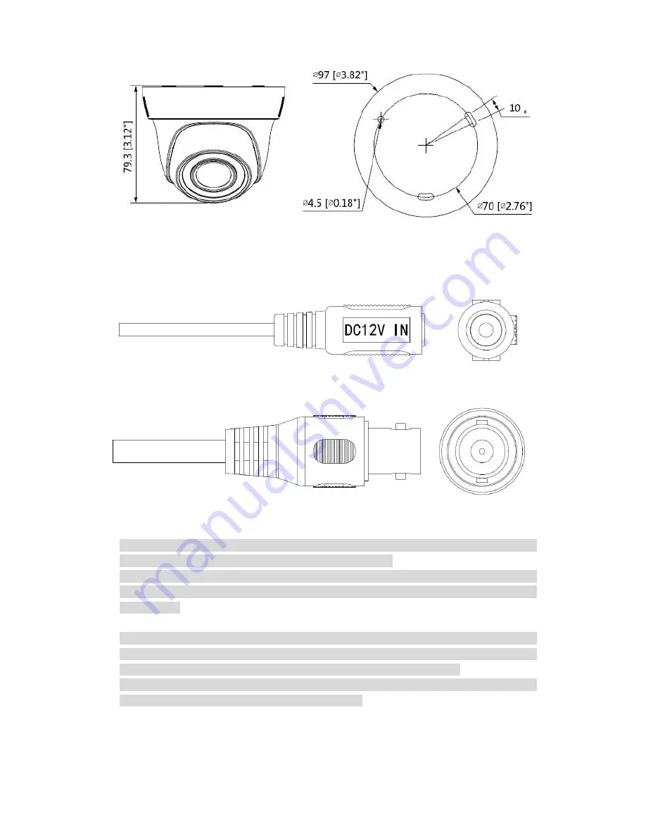
Dahua A User Manual Download Page 8


Figure 2-7 


The device ports include one DC12V power input port and one BNC video output port.  

Please refer to Figure 2-8 for DC12V power input port.  


Figure 2-8 

Please refer to Figure 2-9 for video output port.  


Figure 2-9 

Note  


Video output port outputs HDCVI HD video by default. HD/SD output can be switched via 

UTC Controller or OSD menu 

Advanced 

Video Output.  


For  PoC  models,  the  port  can  realize  both  power  input  via  coax  and  video  output  at  the 

same  time  during  PoC  power  supply.  PoC  can  be  supported  only  in  the  HDCVI  video 

output mode. 

Warning 


Any device is not supported to be connected between the camera and PoC XVR when the 

camera is in the condition of PoC power supply, including UTC, Balun, optical transceiver, 

distributor and convertor etc. Otherwise it may burn the connected device. 


Please  do  not  dismantle  the  device  during  normal  operation;  otherwise  it  may  cause 

danger to both device and users due to high voltage. 

Summary of Contents for A

Page 1: ...HDCVI Camera User s Manual Version 1 0 0...

Page 2: ...l Introduction 1 1 1 Overview 1 1 2 Features 1 2 Device Framework 2 3 Installation 5 Model A 5 Model B1 and B2 6 Model C 7 Model D 8 Model E 9 Model F 10 4 Menu 12 4 1 HCVR Settings 12 4 2 Menu Operat...

Page 3: ...device 2 Environment Please don t aim the device at strong light such as lighting sunlight and so on to focus Please transport use and store the device within the range of allowed humidity and temper...

Page 4: ...l is just for reference The manual will be regularly upgraded according to the product update the upgraded content will be added in the manual without prior announcement Please contact the supplier or...

Page 5: ...ries support RG59 coaxial cable transmission without any loss The distance is over 500m PoC power supply supports transmission distance up to 400m for 1080P and 300m for 4MP via RG59 Support HDCVI HD...

Page 6: ...2 2 Device Framework See Figure 2 1 for the dimension of model A Figure 2 1 See Figure 2 2 and Figure 2 3 for the dimension of model B1 and model B2 Figure 2 2 Figure 2 3...

Page 7: ...Figure 2 4 for the dimension of model C Figure 2 4 See Figure 2 5 for the dimension of model D Figure 2 5 See Figure 2 6 for the dimension of model E Figure 2 6 See Figure 2 7 for the dimension of mo...

Page 8: ...r PoC models the port can realize both power input via coax and video output at the same time during PoC power supply PoC can be supported only in the HDCVI video output mode Warning Any device is not...

Page 9: ...s of the device pedestal with the expansion bolt fixing holes of the installation surface insert the self tapping screws into the expansion bolts and fasten them firmly to fix the pedestal on the inst...

Page 10: ...delivered from factory it has to adjust clockwise when adjusting Zoom end for the first time 2 It has to twist slowly when adjusting Focus end you need to check the image definition when twisting Foc...

Page 11: ...fixing holes of the installation surface insert the self tapping screws into the expansion bolts and fasten them firmly to fix the pedestal on the installation surface if it is top outlet pull the ca...

Page 12: ...e pedestal with the expansion bolt fixing holes of the installation surface insert the self tapping screws into the expansion bolts and fasten them firmly to fix the pedestal on the installation surfa...

Page 13: ...ust pedestal location if it is side cable outlet then pull the cable through the side outlet cable slot Align the bolt fixing holes of the device pedestal with the expansion bolt fixing holes of the i...

Page 14: ...t fixing holes of the installation surface insert the self tapping screws into the expansion bolts and fasten them firmly to fix the pedestal on the installation surface if it is top outlet pull the c...

Page 15: ...osure on the device pedestal Step 3 Install the rotation ring after the enclosure is fixed on the pedestal together with the dome body make sure the location of pedestal cable exit hole is in accordan...

Page 16: ...u Setting System PTZ you need to select the channel number for access and set control mode as HDCVI and the protocol as HD CVI Click Save button to save current setup See Figure 4 1 Figure 4 1 4 2 Men...

Page 17: ...tton functions Button Function Open menu Select menu item Select menu value Sheet 4 1 4 3 Set Audio Coax From Main Menu Setting Camera Encode Encode you need to set Audio Format as G711a and the Audio...

Page 18: ...output Note This manual is for reference only Slight difference may be found in the user interface All the designs and software here are subject to change without prior written notice All trademarks a...

Reviews: