background image

Quick Start Guide 

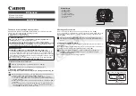
Table 1-2 Description of Alarm I/O port 

Port Name 

Description 

ALARM_IN 

Receives the switch signals of external alarm source. 


Connect different alarm input devices to the same 
ALARM_IN_GND port. 

ALARM_IN_GND 

ALARM_OUT 

Outputs alarm signals to alarm devices. 


When connecting to alarm device, only the ALARM_OUT port and 
ALARM_OUT_GND port with the same number can be used 
together. 

ALARM_OUT_GND 

1.2 Connecting Alarm Input/Output 

The camera can connect to external alarm input/output devices through the digital input/output 
port. 


Alarm input/output is available on select models. 

Procedure 

Step 1 

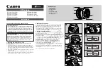
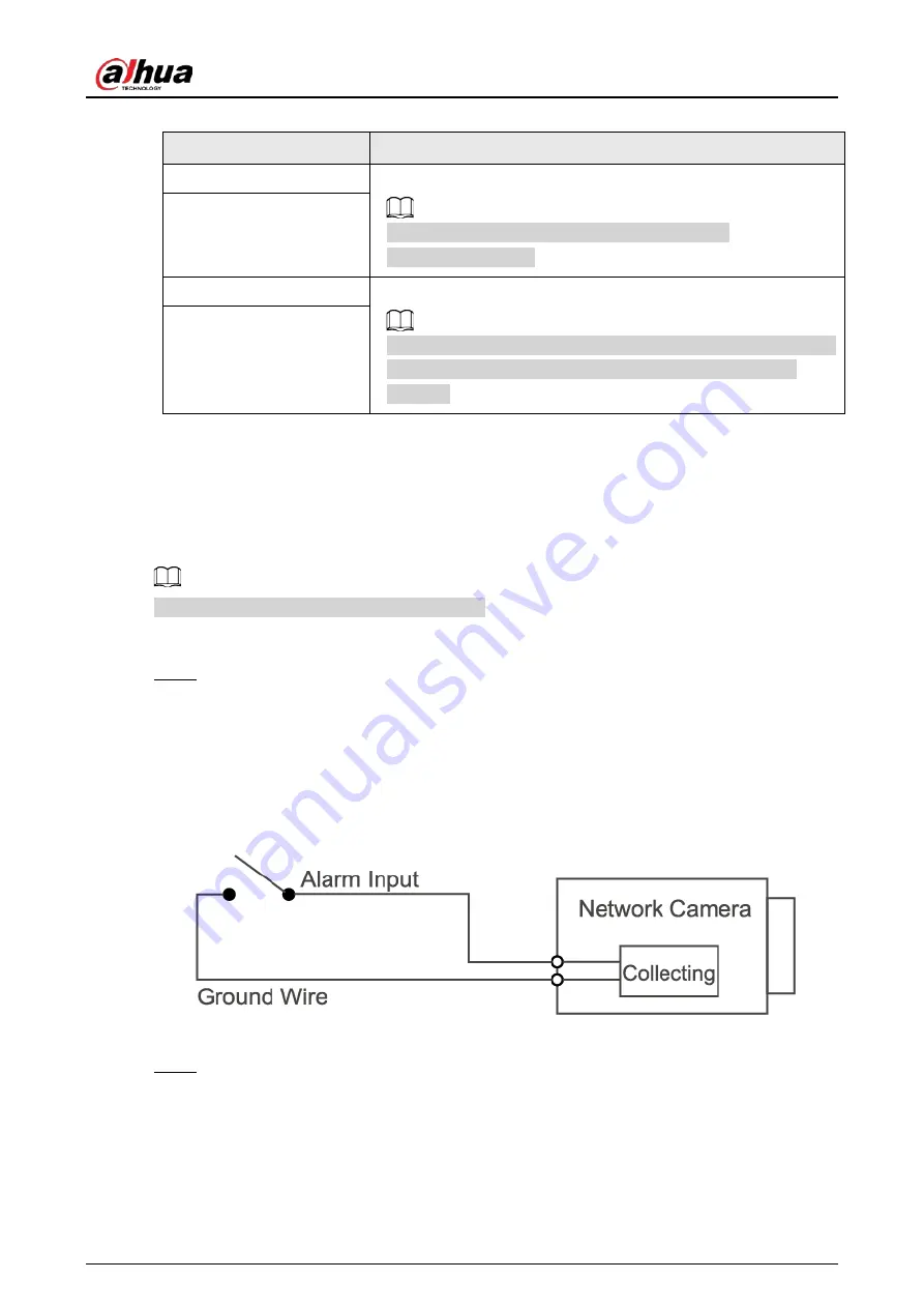
Connect the alarm input device to the alarm input end of the I/O port. See Figure 1-2. 
The device collects different statuses of the alarm input port while the input signal is idling 
and being grounded. 

  Device collects logic "1" when the input signal is connected to +3 V to +5 V or idling. 

  Device collects logic "0" when the input signal is grounded. 

Figure 1-2 Alarm input 
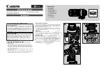
 

Step 2 

Connect the alarm output device to the alarm output end of the I/O port. The alarm output 
is an open-drain output, which works in the following modes. 

  Mode A: level application. The alarm outputs high and low level signals, and the alarm 

outlet is OD, which requires external pull-up resistance (10 K Ohm typical) to work. The 
maximum external pull-up level is 12 V, maximum port current is 300 mA, and the 
default output signal is high-level (external pull-up voltage). The default output signal 

Summary of Contents for DH-IPC-HFW3

Page 1: ...Bullet Network Camera Quick Start Guide V1 0 1 ZHEJIANG DAHUA VISION TECHNOLOGY CO LTD...

Page 2: ...protect the legitimate rights and interests of other people by implementing measures which include but are not limited Providing clear and visible identification to inform people of the existence of t...

Page 3: ...er software if the manual in PDF format cannot be opened All trademarks registered trademarks and the company names in the manual are the properties of their respective owners Please visit our website...

Page 4: ...fety code and standards and check whether the power supply is correct before operating the device Please follow the electrical requirements to power the device When selecting the power adapter the pow...

Page 5: ...res from being walked on or squeezed particularly at plugs power sockets and the point where they exit from the device Do not directly touch the photosensitive CMOS Use an air blower to clean the dust...

Page 6: ...tergent and then wipe the surface dry Do not use volatile solvents such as ethyl alcohol benzene diluent or abrasive detergents on the device to avoid damaging the coating and degrading the performanc...

Page 7: ...Camera 4 2 2 Changing the Device IP Address 5 2 3 Logging in to the Webpage 5 3 Operating with DMSS 6 4 Installation 7 4 1 Packing List 7 4 2 Dimensions 7 4 3 Installing the Camera 8 4 3 1 Installatio...

Page 8: ...d or behave abnormally if power is not correctly supplied 2 Ethernet port Connects to the network through a network cable Do not connect both network cable and Wi Fi at the same time 3 RS 485 Update t...

Page 9: ...t device to the alarm input end of the I O port See Figure 1 2 The device collects different statuses of the alarm input port while the input signal is idling and being grounded Device collects logic...

Page 10: ...c relay Figure 1 3 Alarm output Step 3 Log in to the webpage and then configure the alarm input and alarm output in alarm settings The alarm input on the webpage corresponds to the alarm input end of...

Page 11: ...he same network segment Carefully plan the network segment for the device The following figures and pages are for reference only 2 1 Initializing the Camera Procedure Step 1 Search for the device that...

Page 12: ...Step 2 Select the devices whose IP addresses need to be changed and then click Modify IP Step 3 Configure IP address Static mode Enter Start IP Subnet Mask and Gateway and then the IP addresses of the...

Page 13: ...t pattern Indicator Status Device Status Red light on Booting Device error Green light on Operating properly Step 3 Tap button on the upper right corner of DMSS home screen to scan the QR code on the...

Page 14: ...List Tools required for installation such as the electric drill are not included in the package The operation manual and information on the tools are on the disk or the QR code Figure 4 1 Packing lis...

Page 15: ...hods 4 3 2 Installing the Antennas Figure 4 4 Install the antennas 4 3 3 Optional Installing the SD Card SD card slot is available on select models Disconnect the power before installing or removing t...

Page 16: ...least three times the weight of the camera and bracket Figure 4 6 Cable going through the side cable tray Figure 4 7 Cable going through the mounting surface 4 3 5 Optional Installing the Waterproof C...

Page 17: ...waterproof connector 4 3 6 Adjusting the Lens Angle Due to the detection requirement of infrared detector PIR we recommend you install the device at the height of 2 m to 3 m from the ground and the ho...

Page 18: ...Quick Start Guide...

Reviews: