background image

Quick Start Guide 

12 

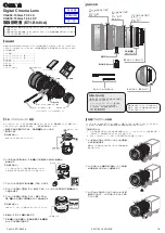
Figure 3-10 Lens installation (model L3) 


Summary of Contents for D-IPC-HUM8441-E1-L1

Page 1: ...Pinhole Network Camera Quick Start Guide ZHEJIANG DAHUA VISION TECHNOLOGY CO LTD V1 0 1...

Page 2: ...protect the legitimate rights and interests of other people by implementing measures which include but are not limited Providing clear and visible identification to inform people of the existence of t...

Page 3: ...er software if the manual in PDF format cannot be opened All trademarks registered trademarks and the company names in the manual are the properties of their respective owners Please visit our website...

Page 4: ...safety code and standards and check whether the power supply is correct before operating the device Please follow the electrical requirements to power the device When selecting the power adapter the p...

Page 5: ...oint where they exit from the device Do not directly touch the photosensitive CMOS Use an air blower to clean the dust or dirt on the lens The dome cover is an optical component Do not directly touch...

Page 6: ...t use volatile solvents such as ethyl alcohol benzene diluent or abrasive detergents on the device to avoid damaging the coating and degrading the performance of the device The dome cover is an optica...

Page 7: ...nings III 1 Introduction 1 1 1 Cable 1 1 2 Connecting Alarm Input Output 3 2 Network Configuration 5 2 1 Initializing the Camera 5 2 2 Changing the Device IP Address 6 2 3 Logging in to Web Page 6 3 I...

Page 8: ...Cable Waterproof all the cable joints with insulating tape and waterproof tape to avoid water damage and prevent short circuits from occurring For details see the FAQ manual Figure 1 1 Front panel 1 c...

Page 9: ...eo input Connect to the lens to get the image data 1 channel lens is available on select models and the lens should be purchased separately 5 Ethernet port Connects to network with network cable Provi...

Page 10: ...through digital input output Alarm input output is available on select models Step 1 Connect the alarm input device to the alarm input end of the I O port Device collects different status of alarm inp...

Page 11: ...larm input end of the I O port There will be high level and low level alarm signals generated by the alarm input device when an alarm occurs Set the input mode to NO default if the alarm input signal...

Page 12: ...work segment Carefully plan the usable network segment for the device The following figures and pages are for reference only 2 1 Initializing the Camera Step 1 Search for the device that needs to be i...

Page 13: ...devices whose IP addresses need to be changed and then click Modify IP Step 3 Configure IP address Static mode When you select Static you need to enter Start IP Subnet Mask and Gateway The IP addresse...

Page 14: ...List Tools required for the installation such as the electric drill are not included in the package The operation manual and information are on the disk or the QR code Figure 3 1 Packing list 3 2 Dime...

Page 15: ...Quick Start Guide 8 Figure 3 3 Model L1 unit mm inch Figure 3 4 Model L3 unit mm inch Figure 3 5 Model L4 unit mm inch...

Page 16: ...t Guide 9 Figure 3 6 Model L5 3 6 mm unit mm inch Figure 3 7 Model L5 2 8 mm unit mm inch 3 3 Installing the Camera The camera adopts a detachable design and the lens and the back end device should be...

Page 17: ...hen power on the camera When installing or removing the lens make sure that the power is cut off otherwise device abnormality or damage could occur Make sure that the mounting surface is strong enough...

Page 18: ...Quick Start Guide 11 Figure 3 9 Lens installation model L1...

Page 19: ...Quick Start Guide 12 Figure 3 10 Lens installation model L3...

Page 20: ...Quick Start Guide 13 Figure 3 11 Lens installation model L4 and model L5...

Page 21: ...Quick Start Guide...

Reviews: