background image

Quick Start Guide 

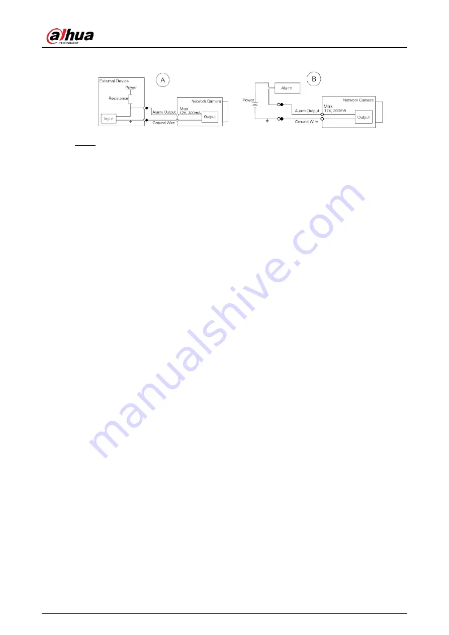
Figure 1-3 Alarm output 


Step 3 

Log in to web interface, and configure alarm input and alarm output in alarm setting. 

  The alarm input on the web interface is corresponding to the alarm input end of the I/O 

port. There will be high level and low level alarm signal generated by the alarm input 
device when alarm occurs, set the input mode to "NO" (default) if the alarm input signal 
is logic "0" and to "NC" if the alarm input signal is logic "1". 

  The alarm output on the web interface is corresponding to the alarm output end of the 

device, which is also alarm output end of the I/O port. 

Summary of Contents for D-IPC-HDBW3841EP-S-0280-S2

Page 1: ...Dome Network Camera Quick Start Guide ZHEJIANG DAHUA VISION TECHNOLOGY CO LTD V1 0 1...

Page 2: ...imate rights and interests of other people by implementing measures which include but are not limited Providing clear and visible identification to inform people of the existence of the surveillance a...

Page 3: ...er software if the manual in PDF format cannot be opened All trademarks registered trademarks and the company names in the manual are the properties of their respective owners Please visit our website...

Page 4: ...umidity and temperature Heavy stress violent vibration or water splash are not allowed during transportation storage and installation Pack the device with standard factory packaging or the equivalent...

Page 5: ...adopting measures which include but not limited to using strong password changing password regularly upgrading firmware to the latest version and isolating computer network For some devices with old...

Page 6: ...guration 4 2 1 Initializing Device 4 2 2 Changing Device IP Address 6 2 3 Logging in to Web Interface 7 3 Installation 8 3 1 Packing List 8 3 2 Dimensions 8 3 3 Installing Camera 9 3 3 1 Installation...

Page 7: ...Provides power to the device with PoE PoE is available on select models 2 Power port Inputs 12 VDC power Be sure to supply power as instructed in the manual Device abnormity or damage might occur if p...

Page 8: ...lects logic 1 when input signal is connected to 3 V to 5 V or idling Device collects logic 0 when input signal is grounded Figure 1 2 Alarm input Step 2 Connect alarm output device to the alarm output...

Page 9: ...alarm input end of the I O port There will be high level and low level alarm signal generated by the alarm input device when alarm occurs set the input mode to NO default if the alarm input signal is...

Page 10: ...res are for reference only 2 1 Initializing Device Step 1 Double click ConfigTool exe to open the tool Step 2 Click Step 3 Click Search Setting Figure 2 1 Setting Step 4 Select the searching way Curre...

Page 11: ...Step 7 Select the devices to be initialized and then click Initialize If you do not provide the linked information for password reset you can reset the password only through XML file When initializin...

Page 12: ...e devices at one time This section is based on changing IP addresses in batches Changing IP addresses in batches is available only when the corresponding devices have the same login password Step 1 Do...

Page 13: ...rom DHCP server when you select DHCP Step 4 Click OK 2 3 Logging in to Web Interface Step 1 Open IE browser enter the IP address of the device in the address bar and then press Enter key If the setup...

Page 14: ...The tool required for the installation such as electric drill is not provided in the package The operation manual and related tool information are contained in the disk or the QR code Figure 3 1 Packi...

Page 15: ...on method 3 3 2 Installing SD Card SD card slot is available on select models Disconnect the power before installing or removing the SD card Do not open the cover for a long time to avoid spray in cam...

Page 16: ...hing camera 3 3 4 Attaching Camera Make sure that the mounting surface is strong enough to hold at least three times the weight of the camera and bracket Remove the protective film after finishing ins...

Page 17: ...uide 11 Figure 3 7 Cable going through the mounting surface 3 3 5 Optional Installing Waterproof Connector This part is needed only when a waterproof connector comes with the camera and the camera is...

Page 18: ...Quick Start Guide 12 Figure 3 8 Install waterproof connector 3 3 6 Adjusting Lens Angle Figure 3 9 Adjust lens angle...

Page 19: ...Quick Start Guide...

Reviews: