8
6. Insert a self-tapping screw into each hole on the camera base and secure to an expansion bolt.
7. Connect the external cables from the camera to the appropriate cables for Ethernet and power.
8. Supply power to the camera.
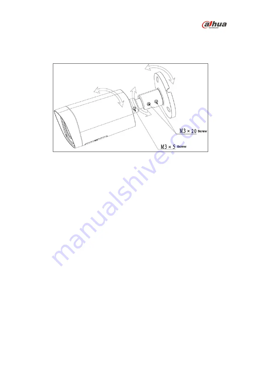
9. Adjust the monitoring direction of the camera.
Figure 4-2
a. Loosen the three hex screws along the shaft of the camera
b. Position the camera by tilting, twisting, and rotating the camera to achieve the desired view.
c. Tighten each hex screw to set the camera position.


