


7.Electrical Interface
© 2023 China Daheng Group, Inc. Beijing Image Vision Technology Branch 120
Storage time (ts): the response time from OUTPUT1 decreases to 50% of amplitude to LINE1+ rises
to 10% of amplitude
Rising time (tr): the response time for LINE1+ to rise from 10% of the amplitude to 90%
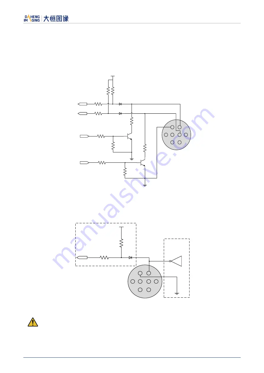
7.3.3.
GPIO 2/3 (Bidirectional) Circuit
1
2
8
7
6
4
5
3
3.3V
Line2
Line3
FPGA INPUT2
FPGA INPUT3
FPGA OUTPUT2
FPGA OUTPUT3
PTC
PTC
Figure 7-7 GPIO 2/3 (bidirectional) circuit
7.3.3.1.
Line2/3 is Configured as Input
When Line2/3 is configured as input, the internal equivalent circuit of camera is shown in Figure 7-8, taking
Line2 as an example:
1
2
8
7
6
4
5
3
3.3V
Line2
INPUT2
External
circuit
Camera internal circuit
Figure 7-8 Internal equivalent circuit of camera when Line2 is configured as input
To avoid the damage of GPIO pins, please connect GND pin before supplying power to Line2/3.
Logic 0 input voltage: 0V~+0.6V(Line2/3 voltage)