background image

Chapter 12 Instructions on Loop Embroidery 

BECS-D19 User’s Manual


      133 

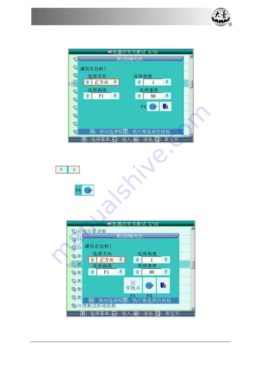
12.5.4 Test D-axis Motor 


Operation: 

1


Use  left or right direction keys on the keyboard to move the red box to select 

  and then press up or down keys to select direction, angle, curve and 

rotation speed. Pull bar to start test; 

2


Press 

  to return to origin; 

3


Press “ESC” to exit. 

12.5.5 Text H-axis Motor 


Summary of Contents for BECS-D19

Page 1: ...Computerized Control System for Embroidery Machine BECS D19 Version 2019 02 USER S MANUAL...

Page 2: ......

Page 3: ...Item Status 13 2 5 How to Input Number Letter and Symbol 13 2 6 How to Move Cursor 14 2 7 Basic Embroidery Procedure 14 2 8 Normal Embroidery Returning and Patch Embroidery 20 2 9 Relationship betwee...

Page 4: ...37 4 4 Pattern Preview 37 4 5 Copy Memory Pattern 39 4 6 Delete Memory Pattern 41 4 7 Applique Pattern Setting 42 4 8 Satin Stitch Compensation 44 4 9 Edit Combined Pattern 45 4 10 Devide Pattern 47 4...

Page 5: ...ore Functions for Setting Other Parameters 60 5 3 Initialize Machine Parameters 61 5 4 Machine Authorization Management 61 5 4 1 Unlock Change Administrator Password 62 5 4 2 Administrator Unlocks the...

Page 6: ...o Search 70 6 1 4 Needle Stops Down 70 6 1 5 Set another Start 72 6 1 6 Set B Point 72 6 1 7 Operation of Air Frame Sequin and Coiling Devices 74 6 1 8 Upper Thread Holding Operation 74 6 2 Other Assi...

Page 7: ...2 3 Generate Pattern from Pattern Outline 90 7 2 4 Generate Patch Position by Frame moving then Embroider 91 7 2 5 Embroider a Cross at Current Position 92 7 2 6 Embroider a Line from Frame moving En...

Page 8: ...0 2 Embroider Sequin 111 10 3 Input Sequin Pattern 111 10 4 Sequin Embroidery Parameter Setting 112 10 5 Manual Operation of Sequin Embroidery 114 10 6 Sequin Applique 115 Chapter 11 Instructions on C...

Page 9: ...ings 128 12 5 Machine Debugging 129 12 5 1 Thread Loosing Position Adjustment 130 12 5 2 Needle Height Adjustment 131 12 5 3 Color changing Position Adjustment 132 12 5 4 Test D axis Motor 133 12 5 5...

Page 10: ...k Operation Specification 150 Appendix 3 Error List 151 Appendix 4 Loop Embroidery Parameter List 154 Appendix 5 Loop Embroidery Error List 158 Appendix 6 Network Connection Instructions 159 Note chan...

Page 11: ...ious injury Forbidden Don t expose the machine to humidity dust corrosive gas either at work or in storage in order to prevent electric shock or fire Forbidden Don t store or operate the machine in vi...

Page 12: ...t put any strength on cables Make sure the turning point of cable is well protected Add pipes to increase insulating capability Caution Please confirm that The computerized control equipment involved...

Page 13: ...ll reboot the LCD 3 Super large Memory Capacity The memory space reaches 2M and up to 800 patterns can be stored which can satisfy the demands of various users for memory space 4 Max 2 Million Stitche...

Page 14: ...stop code and when the machine embroiders to the patch position it will halt and move out of frame for patching Then user can pull the operation bar to return and continue embroidering 13 Brake Adjust...

Page 15: ...r delete certain stitch at certain point New patterns can be created by this function too 23 Speed Adjustment The highest speed for embroidery can be set in advance During embroidery speed will change...

Page 16: ...ppy dirve C How to Use USB Disk Please pay close attention to electrostatic phenomenon Don t forget to discharge the metal structure or frame by hand before plugging in out the USB disk USB disk featu...

Page 17: ...dery 3 Task Shift If user opens several interfaces use this key to shift among these interfaces in order 3 Speed Adjustment Press to reduce or increase the current embroidering speed respectively 3 Ma...

Page 18: ...to start embroidery When machine stops press this key to releast the confirmation status and the system changes from confirmation status into ready status 3 Exit Press this key to exit the current ope...

Page 19: ...splayed 4 Pattern Information Information related to the embroidered pattern is displayed 5 Color changing Order and Current Needle Position 6 Machine Status Information in the order of left to right...

Page 20: ...ill arrive in position 3 Go to stop point When the machine stops press the key Manual Frame moving to move the frame e g in case of patching Then press this key and the frame will automatically return...

Page 21: ...l start In this status press related needle position key to select a position Pull bar to start embroidering When meeting the color changing code system stops the machine automatically and displays Th...

Page 22: ...and the frame will move back along the pattern trace When machine stops press this key to change to high speed idling status High speed idling System is now in high speed idling status Pull bar but m...

Page 23: ...Press this key to enter operation interface of positioning idling Chapter7 3 Pattern border operation Press this key to enter pattern border operation interface Chapter7 3 Change design direction Pre...

Page 24: ...e the cursor will move consecutively among each item of the present operation interface 2 7 Basic Embroidery Procedure The machine embroiders based on the patterns in its memory The following is the b...

Page 25: ...press in the main interface to enter it If the interface is opened but the current interface is about another function press the blue task shift key on the panel to enter the pattern management inter...

Page 26: ...e operation interface of pattern parameter and color changing order 2 Set applique embroidery to enter pattern management interface where user can press to set applique following the hints 3 Check the...

Page 27: ...ant operation Then press at the appearance of the following hint window Then embroidery release will change into embroidery confirmation which indicates that the system has enter embroidery confirmati...

Page 28: ...right end is to embroider slowly and releasing the bar will resume the normal speed Pulling the bar to left is to stop embroidery including low speed idling and high speed idling F Manual Operation 1...

Page 29: ...n to the stop point 8 Positioning idling Use this function after embroidery confirmation Positioning idling enables the machine to move to the designated position according to the user s need without...

Page 30: ...e frame can return continuously even when you release the bar This may be different for different machine types When the frame returns continuously pull the bar to left again the frame will stop retur...

Page 31: ...including low speed idling and high speed idling Running Status Pulling the bar to the right end is to embroider slowly and releasing the bar will resume the normal speed Pulling the bar to left is t...

Page 32: ...e the switch it returns to the middle Meanwhile status light on this head will turn red to indicate that patching mode is available on this head 2 12 Working Status The machine has three working statu...

Page 33: ...atted and outputted Pattern formats like DSB DST and DSZ can be read For data output pattern data will be saved as DSB format 3 1 Disk Selection Since the system supports more than one storage device...

Page 34: ...nformation 3 Single Multiple Seletion Shift between single selection and multiple selection 4 Select All Select all items with the current directory only available under multiple selection mode 5 Patt...

Page 35: ...play the current page and total page number 16 Memory Capacity Display the memory capacity and the remaining space 17 Pattern Date Only pattern file can be displayed 18 Pattern Stitch Number Display t...

Page 36: ...ns 20 objects If the objects are more than 20 in current directory please turn to another page to look for other patterns You can also use to find pattern in other pages The selected object has a blue...

Page 37: ...and word information of the selected pattern will be showed within the blue square 2 Single multiple selection switch When user selects the objects the system is in single or multi selection mode In s...

Page 38: ...the user has to select files from one or more disks first and then input the pattern number and name for the file to be saved 1 Select one or more files in the disk 2 Press and the system will requir...

Page 39: ...r After the modification press and the system will automatically enter the item for changing pattern name Please input the name following the hints 4 Press and the system will save the pattern data in...

Page 40: ...s step user can press to quit 3 6 Directory Operation 1 Enter the directory Select the directory and press System reads the item list of the directory and refreshes the interface 2 Return to previous...

Page 41: ...o delete and press to quit Note If user chooses to select the directory for deletion system will delete all the files and sub directory in this directory If a file has the property of only read or dis...

Page 42: ...ning information for disk formatting and formatting process bar as well as Start and Return button 3 Press System will begin to format the disk and show the speed with a process bar After formatting t...

Page 43: ...emory Pattern Management Interface and Other Instructions Press in the main interface to enter the memory pattern management interface The memory pattern management interface includes pattern display...

Page 44: ...Chapter 4 Memory Pattern Management 34 BECS D19 User s Manual...

Page 45: ...urpose of selection 4 Page Information Display the current page number and total number of pages 5 Select Pattern In embroidery preparation status press this key to enter modification interface of pat...

Page 46: ...pattern 18 Generate Pattern by Parameters To generate pattern by embroidery parameters 19 Generate Pattern by Frame moving Press this key to enter the interface for generating pattern by frame moving...

Page 47: ...cancel the selection 4 3 Select Pattern for Embroidery 1 Select a new pattern for embroidery and make sure system is in preparation status 2 In the main interface press to enter memory pattern manage...

Page 48: ...w Area Display the selected pattern on the patternated way and speed 2 Pattern Information Display the pattern information 3 Help Display the help menu 4 Redraw Display the selected pattern again 5 Si...

Page 49: ...e to open pattern preview interface 4 Press in the pattern preview area to control the pattern size and press to control the pattern display position Press to locate the pattern to the center Press to...

Page 50: ...number and press to confirm the change 5 System will automatically enter pattern name modification area If user wants to change it input the new pattern name 6 Press to confirm the change and conduct...

Page 51: ...from the machine 1 Press in the main interface to enter memory pattern management interface 2 Select patterns for deletion User can select one or several patterns 3 Press to enter the operation interf...

Page 52: ...ll the bar for embroidery Automatic moving frame out has two ways by moving frame to the offset point or by setting the moving distance The operation is as follows firstly set appliqu embroidery funct...

Page 53: ...op code 5 Option list Type of appliqu at this position 1 No appliqu 2 Set offset position 3 Appliqu distance 6 Frame out distance Select the appliqu distance frame out 2cm to 99cm or 2cm to 99cm 7 Whe...

Page 54: ...em will return to the pattern operation selection interface 4 8 Satin Stitch Compensation This operation is to adjust the satin stitch width in the pattern according to need 1 Press in the main interf...

Page 55: ...he combined pattern into normal pattern by using the edit function so as to check and embroider the pattern 1 Press in the main interface to enter memory pattern management interface 2 To edit the sav...

Page 56: ...6 BECS D19 User s Manual 6 Press to save the combined pattern 7 Input the pattern number and name and press to save the pattern or press to quit saving the combined pattern system will return to the p...

Page 57: ...em 5 Press to divide the pattern into two new patterns or press to cancel the operation system will return to the pattern operation selection interface 4 11 Integrate Patterns This function is to comb...

Page 58: ...ry pattern management interface 2 Select the target pattern in the pattern image area of the memory pattern management interface 3 Press to enter the operation interface for generating high speed patt...

Page 59: ...rn operation selection interface 4 14 Generate Pattern by Parameters This operation is to change the setting of color changing order and normal parameters such as scaling and repetition which is attac...

Page 60: ...broider the boundary of a pattern before embroidering it so as to provide convenience to the later appliqu operation This function can create such a pattern and you can select the new pattern to embro...

Page 61: ...ber and pattern name and then press to confirm for generation 7 Press to quit the operation and return to previous interface 4 16 Generate Outline Pattern from Normal Pattern This function is to creat...

Page 62: ...doesn t want to use the default value press to change by keyboard 4 Press to generate a new pattern with different stitch length or press to quit the operation system will return to the pattern operat...

Page 63: ...n under embroidery the non embroidery parameter setting interface will be displayed For setting parameters please refer to 5 1 and 7 1 After setting press the key to save the parameters with the patte...

Page 64: ...patterns is at the corresponding operation interface under the memory pattern management interface See Chapter 4 Press in the main interface to enter the following interface As the picture shows when...

Page 65: ...set the X Scales as an example and give the definitions of other parameters Read 5 1 3 as reference 5 1 1 Pattern Direction 5 1 2 Rotating Angle This parameter can be used to make the pattern rotate i...

Page 66: ...the parameter setting window 2 Modify the value of X Scaling Press the number keys in the parameter setting window to change the scaling in X direction User can press to cancel the last input digit No...

Page 67: ...explains the meaning of this parameter 5 1 8 Priority Mode There are two modes rotating priority and scaling priority When user has selected the Rotating Priority the pattern will rotate first and the...

Page 68: ...changed unless the factory password is unlocked When a parameter is labeled by a number then it can be changed by pressing 5 2 1 Setting Procedure for Other Parameters The setting procedure is similar...

Page 69: ...Embroidery Head Shuttle Rebounding Number 1 9 and press to display the following interface 4 Input the needle number according to machine type and press to save the setting or press to quit system wil...

Page 70: ...color changing 2 when a new pattern is embroidered with manual color changing once the color changing order is set for the pattern To use this function user should set the parameter Save Manual Color...

Page 71: ...d all manufacturer authorized machine parameters are recovered to the values saved by the manufacturer and other parameters are initialized to the default values 4 When both manufacturer password and...

Page 72: ...re parameters 5 4 1 Unlock Change Administrator Password When the machine is sold by manufacturer it s without password namely user can change all parameters After password setting general user can t...

Page 73: ...password must be input two times 5 4 2 Administrator Unlocks the Machine After machine administrator motifies the password the machine is locked General user can t modify the machine application param...

Page 74: ...aved optimized parameters press the key of administrator recovers optimized parameters and system will hint the operation User can follow the hint and confirm the operation to recover the previously s...

Page 75: ...urer all administrator authorized machine application parameters are recovered to the values set by administrator and other parameters are initialized to their default values 5 When that manufacturer...

Page 76: ...password move the cursor to corresponding item and press to do the corresponding operation 5 8 1 Set Parameters The setting is similar to that of other normal parameters please refer to Appendix 1 5 8...

Page 77: ...r X Y servo drivers in the controller will be saved and applied to the servo driver after user performs the operation And the parameters can be saved even power is off 5 8 4 Recover Default Driver Par...

Page 78: ...ce If the frame origin has been set see 6 2 3 in the embroidery confirmation status user can set pattern start point 6 1 1 Resume Pattern Origin If the current pattern has start point user can use thi...

Page 79: ...before press to cancel the operation 6 1 2 Save Pattern Origin 1 Move the frame to the embroidery pattern origin 2 Follow the above instruction and enter assistant embroidery operation interface 3 Mov...

Page 80: ...frame and move to that position press to cancel the operation 3 System returns to the main interface 6 1 4 Needle Stops Down This function is used for the embroidery of the entire fabric The needle w...

Page 81: ...e operation 4 Release the cloth move frame and confirm the operation After releasing the cloth user need move frame to appointed position and press to confirm If you press the operation will be cancel...

Page 82: ...her start The system will ask the user to move the frame to the other start and display the coordinates of X and Y User need press the frame moving key to move the frame to the other start and press t...

Page 83: ...e trimming action instead of moving frame to B point when you press slow motion button after thread breakage only when frame is moving under B point b zone that is outside the inner edge of the table...

Page 84: ...e switch of air valves V1 V4 are for quilt embroidery Other sequin and special embroidery operations are detailed in different chapters 6 1 8 Upper Thread Holding Operation The operation is used for t...

Page 85: ...1 Check Embroidery Parameter User can check the current pattern s parameters and some machine conditions 1 Press in the main interface to enter the interface of other assistant manangement operation 2...

Page 86: ...d press 3 System displays the statistic data interface In the above interface the statistic data is displayed in chart User can press to clear the value and press to return 6 2 3 Frame Protection Sett...

Page 87: ...origin again If you hope the system automatically set the frame origin press auto farme origin and the system will move the frame automatically and set the origin according to the limit switch So plea...

Page 88: ...frame origin 6 2 5 Set Embroidery Scope in Software This function is to set embroidery scope in software and make system embroider pattern in the set range It s the basis to locate pattern in the cen...

Page 89: ...e after you confirm the top right corner of soft limit press to confirm 5 Move frame and input the coordinates of bottom left corner Use frame moving key to move the frame after you confirm the bottom...

Page 90: ...Move the cursor to display or set system clock and press 3 Use number keys to input number or press to select the number to be inputted press to select option 4 Press to confirm or press to return wi...

Page 91: ...e the cursor to the intended language press to confirm or press to quit 6 2 8 Machine Software Information 1 Press in the main interface to enter the interface of other assistant manangement operation...

Page 92: ...gement operation 2 Move the cursor to machine software information and press System will display the help information of the interface press or press to turn page 6 2 10 Machine Test This operation is...

Page 93: ...thread breakage Thread Breakage Statistics Count of Roller Thread Breakage Device Test sequin device on off Sway Zig Rod to 100 Test lift of taping presser foot Test upper thread holding function Thre...

Page 94: ...er will be saved along with the pattern Press in the main interface to enter color changing order interface where user can make the color changing order operation 7 1 1 Input and Repeat Color changing...

Page 95: ...layed in the interface If it is a special embroidery position or sequin embroidery position the system will enter the selection window of sequin and special embroidery For details please refer to oper...

Page 96: ...l embroidery or a sequin embroidery position see related chapters for details If you want to modify the next color you can repeat step 2 Press to save the color changing order or press to exit without...

Page 97: ...ss number keys and to save the input or press to quit without saving 7 1 4 Set Pattern Display Color In order to make the display effect close to the real embroidery pattern the system supports settin...

Page 98: ...bar to be set then press to select the desired color and press to confirm After setting the corresponding color will be displayed at the needle button 3 After setting press to save the needle bar col...

Page 99: ...order range of the current embroidery pattern 1 Move the cursor to check the pattern border and press System will display the border information of the pattern in window 2 Press or to close the window...

Page 100: ...d press System will hint confirmation box 2 Press to confirm and move the frame along the pattern border and the interface will display the movement information Press to cancel 3 After finishing the m...

Page 101: ...ave the outline pattern or press to cancel the operation 7 2 4 Generate Patch Position by Frame moving then Embroider Before embroidering a pattern user may wish to embroider a sign for positioning ap...

Page 102: ...t new pattern number system will automatically provide a number and name and press to confirm and generate the pattern 5 Press to cancel the current operation and return to previous interface 7 2 5 Em...

Page 103: ...in interface Now the label is displayed User can pull bar to embroider a cross After the embroidery system will return to the embroidery preparation status 7 2 6 Embroider a Line from Frame moving End...

Page 104: ...nd point 3 System will generate temporary data of the line and return to the main interface Now system displays on the main interface Pull bar to embroider the line and after that system will return t...

Page 105: ...tern border and return to the main interface after user confirms the operation Now system displays on the main interface Pull bar to embroider the border and after that system returns to the embroider...

Page 106: ...r to embroider the outline and after that system returns to the embroidery preparation status 7 3 Positioning Idling This function is only available in embroidery confirmation status According to the...

Page 107: ...r s Manual 97 7 3 1 Positioning Idling by Forward Stitches 1 Move the cursor to forward stitches and press 2 Input the number of forward stitches System enters the interface of forward stitches User c...

Page 108: ...by Next Color changing Code 1 Move the cursor to next color changing code and press 2 Press again to confirm and system returns to the main interface where user pulls bar to right to idle to the next...

Page 109: ...Chapter 7 Other Operations BECS D19 User s Manual 99 Press to clear the value to 0 or press to cancel the operation User can check the value in the main interface...

Page 110: ...r create a new pattern 8 1 Start Pattern Edit Press in the main interface to enter memory pattern management interface Select the pattern for edit and press to display the following window Press to ed...

Page 111: ...op left while the positioning stitch type on the top right use to shift and the detailed stitch information at the bottom of the interface 1 Pattern editing interface 2 Document operation to save patt...

Page 112: ...stitch in the pattern preview window If the current stitch is not within view system will automatically renew the view to display the current stitch in the centre 1 Stitch Positioning positioned to th...

Page 113: ...rmediate speed and high speed to add satin stitch at the pattern end continuously Move coordinate index to proper position by pressing direction keys Press to add a stitch at present position move coo...

Page 114: ...main interface to enter memory pattern management interface where user can press in order to enter letter pattern operation interface 9 2 Input Letter String and Basic Parameters After entering param...

Page 115: ...s to move cursor to intended font and press to confirm 3 Arrangement arrangement of letters Four types of arrangement are available straight vertical up arc and down arc 4 Letter Interval interval bet...

Page 116: ...during the letter pattern adjustment After setting letter pattern parameters user need press to enter the interface to generate letter pattern in order to adjust letter pattern A The Interface to Gene...

Page 117: ...to display in dark press to move window and letter pattern will move along the window Save used to save the letter pattern being edited Press this key to display the interface to input pattern number...

Page 118: ...r interval e g Reduce Letter Interval reduce letter interval e g D Adjustment of Selected Letter Selection Switch switch the selected letter User has to pick up a certain letter and then he can carry...

Page 119: ...of the generated letter pattern e g Flip Horizontal flip horizontal of selected letter Flip Vertical flip vertical of selected letter Color changing Switch set or cancel color changing before the sele...

Page 120: ...Chapter 9 Letter Pattern Operation 110 BECS D19 User s Manual window input the pattern number and name and then press to save Press to confirm the saving and in case of no more editing press to quit...

Page 121: ...retrieval movement of the linkage to feed sequins into position 2 Separate action of sequin appliqu and sequin feeding device 3 Manual separation of heads or collective sequin feeding at one time 4 S...

Page 122: ...mal sequin pattern the changed sequin pattern will save all the multi sequin as A type sequin If you choose No normal sequin pattern remains as normal sequin pattern while special multi sequin pattern...

Page 123: ...stment range 15 15 It is used to adjust the sequin feeding angle opposite to the main shaft The higher the value the later the feeding time is 3 Sequin Embroidery Auto Start When set as Yes system wil...

Page 124: ...ght Sequin Device 9mm Setting According to actual situation this parameter can be set as single or dual direction with angle range being 5 4 62 2 degree 8 6 Left Right Sequin Device A Size Color Accor...

Page 125: ...e operator to monitor Note when the manual control switch of air valve is in the middle blue lamp is on which indicates a normal condition of sequin embroidery Installation Position of Sequin Switch B...

Page 126: ...manually 5 Coiling Taping and Zigzag functions can be switched at will 6 The presser foot of special embroidery can go up and down automatically or manually This function is only for the machines ins...

Page 127: ...is 18 step 11 3 Parameters and Settings Press in the main interface to enter parameter setting interface where user moves the cursor to special embroidery parameter and then presses to enter the inter...

Page 128: ...ge the setting 6 D42 Angle Compensation of M axis 0 10 The M axis of special embroidery head has mechanical clearance so it will generate the mechanical difference after M axis changes rotating direct...

Page 129: ...Special Embroidery 1 Manual Shift Press in the main interface to enter color changing interface Move the cursor to the icon of corresponding special embroidery press to save selected special embroider...

Page 130: ...e achieved through the setting of color changing position In the main interface press to enter the interface for adjusting color changing order move cursor to input and repeat color changing order or...

Page 131: ...y includes M axis Back to Working Position M axis Back to Zero Position and M axis Manual Operation 1 M axis Back to Working Position Press in the main interface and move cursor to M axis back to work...

Page 132: ...ping presser foot action and press to display the dialogue window Following the hint user can pull bar switch to lift lower the presser foot or pull it again to lower lift the presser foot or press to...

Page 133: ...oot Axis The working progress of the special embroidery presser foot is shown at below The presser foot working height is the distance of the foot s movement at every stitch The presser foot rising he...

Page 134: ...s raised to the limited height by one mono phase AC motor driving the presser foot axis At both the upper and bottom points a proximity switch is installed to adjust the presser foot rising height The...

Page 135: ...ry and chained embroidery auto switch Needle of loop embroidery head automatic action Automatic thread trimming function Needle automatically goes up before manual frame moving and needle goes down be...

Page 136: ...1 means shuttle position a 2 position b 3 position c and so on 4 When current head is looping embroidery head press number keys to display the window of looping embroidery mode and needle bar height s...

Page 137: ...Chapter 12 Instructions on Loop Embroidery BECS D19 User s Manual 127 12 2 2 Loop Embroidery Main Interface Introduction The above picture is the main interface after switch to flat embroidery head...

Page 138: ...itch type L means looping 0 indicates the needle height level 4 is the color changing order list each group consisting of three items shuttle position b stitch type C needle height 0 12 3 Loop Embroid...

Page 139: ...osing drive 6 Thread treatment after trimming and color changing this parameter is used together with thread treatment after trimming with the same effect when set as Yes 7 F48 Flat embroidery head an...

Page 140: ...e loosing motor position and loosing speed In case of abnormal loosing position press left or right direction keys on the keyboard to move the red selection box and when is selected user can use up or...

Page 141: ...ery 2 for chained embroidery 1 for trimming action 0 for trimming knife return 0 or 1 for color changing 12 5 2 Needle Height Adjustment This function allows user to adjust needle height to improve em...

Page 142: ...change of the resistance of singlg circle precision potentiometer User can use left or right direction keys on the keyboard to move the red box to select and then use up or down keys to make the follo...

Page 143: ...D axis Motor Operation 1 Use left or right direction keys on the keyboard to move the red box to select and then press up or down keys to select direction angle curve and rotation speed Pull bar to st...

Page 144: ...reading point Press ESC to exit 12 5 6 Test Main Shaft of Chained Embroidery The operation is the same with that of flat embroidery 12 5 7 Test Main Shaft Encoder of Chained Embroidery The operation i...

Page 145: ...to thread clamp knife out of thread clamp Use left or right direction keys on the keyboard to move the red box to select and then press up or down keys to adjust the trimming angle knife angle into th...

Page 146: ...is looping embroidery head that is is displayed in the main interface press to display the window of assistant embroidery operation and select corresponding item to execute manual operation in order...

Page 147: ...f normal flat embroidery machine When set as loop embroidery head 1 on the keyboard represents shuttle position a 2 position b 3 position c etc After setting the shuttle position the window of looping...

Page 148: ...this time loop embroidery head is in normal embroidery status 2 Put head switch in down position head light off needle lifts to off position and loop embroidery head is shut down 3 Put head switch in...

Page 149: ...axis motor head light and switch control ON Down head board to control trimming motor H axis motor and thread breakage detection Semi independent machine type has two kinds 1 Apart from H axis motor...

Page 150: ...to make cyclic embroidery No No Yes Whether to automatically repeat embroidery at end It often coordinates with repetition or special pattern B04 Whether to display stitch number Yes No Yes C02 Wheth...

Page 151: ...bove Thread Breakage Detection Parameters B05 Breakage detection Yes No Yes B11 Stitch number without detection at start 8 stitches 0 15 stitches B06 Stop after detection Yes No Yes B07 Pull bar after...

Page 152: ...2 30 D19 Use of pneumatic frame Yes No Yes D20 Action interval of pneumatic frame 3 0 15 C74 X direction frame moving angle A 245 230 280 Applicable for all servo high speed machine C75 X direction fr...

Page 153: ...is a servomotor the parameter is usually set as 5 7 C24 Main shaft motor parameter 1 0 30 The parameter is invalid when it s a servomotor When it s an electromagnetic motor increase this parameter val...

Page 154: ...er trimming D06 Rotation after trimming before stop 1 1 2 2 for most machines 1 for mini type or machines with servo motor C23 Action after trimming Y direction frame moving X direction frame moving Y...

Page 155: ...uin device lowering time 3 0 15 Range 0 15 For the machine using air valve to control presser foot 2 3 for the machine with stepping motor to control presser foot 4 5 C34 Sequin device auto lift after...

Page 156: ...None 1 Set the parameter base on sequin device 1 mean number of sequin device driven by one motor D62 Set 3MM of L Sequin Single way 6 40 steps Dual way 6 40 steps D63 Set 4MM of L Sequin Single way...

Page 157: ...me Swing 0 2 10 0 0 2 0 2 10 D50 Zigzag Swing Adjustment 0 0 5 D42 M axis Angle Compensation 0 0 10 D44 M axis Withdrawal Angle 0 0 90 C39 Trimming Mode No No Upper Bobbin Upper bobbin C35 Max Speed L...

Page 158: ...oid Voltage 6 1 10 C41 Server Port Number 1600 1 65535 It is used for setting sever port when it is connected to PC C42 MAC Address 0011223 34455 001111111111 009999999999 It is used for setting the M...

Page 159: ...ustment X parameter available for all servo high speed machine Embroidery Parameter 300 93 650 Frame moving Parameter 1 260 93 650 Frame moving Parameter 2 13 6 50 Parameter 1 30 10 50 Parameter 2 30...

Page 160: ...its of prefix is viewable suffix is 3 digits For instance DST will be displayed as 1 DST 6 Filename displayed in Chinese Support 7 Sub directory operation Support 8 Sub directory limit No limit 9 File...

Page 161: ...not saved 09 Frame software range not set 10 Wrong Password 11 New passwords not same 12 Embroidery pattern not exist 13 Pattern already existed 14 Pattern not exist 15 Fail to open pattern 16 Combin...

Page 162: ...ication failure 51 Pattern read error 52 Edit Forbid after embroidery confirmation 53 Design is too big Can t process 54 Can not format the disk 55 Unsupported operation 56 Disk Error Lower Computer E...

Page 163: ...ck EC26 Trimming not in position EC36 Sequin at down position EC37 Bar switch error EC38 Special embroidery head action overtime EC41 File not exist EC42 File directory full EC43 Memory is full EC44 F...

Page 164: ...breakage detection This function is set by upper computer F43 Looping Angle at Low Speed 0 0 9 Adjust product quality at low speed F49 D axis Start Angle 7 0 15 Set the start angle of D axis F50 H axi...

Page 165: ...tch and flat embroidery stitch F23 Chained Embroidery Frame moving Angle 6 0 10 Adjust action order which will influence product quality F80 Looping Embroidery Frame moving Angle 6 0 10 Adjust this pa...

Page 166: ...ability of motor over load F63 H axis Looping Action Angle 5 0 10 F64 H axis Looping Thread Returning Compensation 5 0 10 F65 Speed Down at Turning 2 1 9 No Trimming Related Parameters F01 Jump and Tr...

Page 167: ...250 Set the off position of head F38 Thread Loosing Method Md02 Md02 e937 It is related to the requirement of drive input signal BBQ2003 is dual impulse input while E937 is single impulse input F48 L...

Page 168: ...ck of thread loosing motor 545 No feedback of color changing motor 546 No feedback of needle bar action 547 No feedback of upper head board 548 No feedback of lower head board 549 No feedback of shaki...

Page 169: ...erminal The Other Terminal Usage a Link switch or HUB to router b Link computer including server and workstation to switch or HUB 2 Making Crossover Cable 1 3 2 6 crossover connection Twisted pair cab...

Page 170: ...nition of IP Address IP address also called Internet address is the sole logic address for computers in the internet Every computer in the internet relies on IP address to mark itself It s like we fin...

Page 171: ...s and subnet mask combine to tell in which network the computer is So the subnet mask is very important If it s wrong it will get the wrong network address Therefore the same network number must be se...

Page 172: ...of embroidery machine 2 PC Connected to Embroidery Machine via HUB In this situation straight through cable is needed to link PC or embroidery machine with HUB 3 Connect the two networks in 2 through...

Page 173: ...tServer 4 IP Address of Embroidery Machine It is the IP address of embroidery machine when it s linked with PC The IP addresses of embroidery machines can t be repeated The network numbers of embroide...

Reviews: