background image

 Air Conditioner Service Manual


44


7

. Precaution 

7

.1 SAFETY RULES AND RECOMMENDATIONS FOR THE INSTALLATION 

z


Read this guide before installing and using the appliance. 

z


During the installation of the indoor and outdoor units the access to the working area should 
be forbidden to children. 

Unforeseeable accidents could happen. 

z


Make sure that the base of the outdoor unit is firmly fixed. 

z


Check that air cannot enter the refrigerant system and check for refrigerant leaks when 
moving  the air conditioner. 

z


Check that air cannot enter the refrigerant system and check for refrigerant leaks when 
moving  the air conditioner. 

z


The ratings of the fuse installed in the built in-control unit are T 5A / 250V. 

z


The user must protect the indoor unit with a fuse of suitable capacity for the maximum input 
current or with another overload protection device. 

z


Ensure that the mains voltage corresponds to that stamped on the rating plate. Keep the switch or 

power plug clean. Insert the power plug correctly and firmly into the socket, thereby avoiding the 
risk of  electric shock or fire due to insufficient contact. 

z


Check that the socket is suitable for the plug, otherwise have the socket changed. 

z


The appliance must be fitted with means for disconnection from the supply mains having a contact 

separation in all poles that provide full disconnection under over voltage category III conditions, and 
these  means must be incorporated in the fixed wiring in accordance with the wiring rules. 

z


The air conditioner must be installed by professional or qualified persons. Do not install the appliance 

at a  distance of less than 50 cm from inflammable substances (alcohol, etc.) Or from pressurized 
containers  (e.g. spray cans). 

z


If the appliance is used in areas without the possibility of ventilation, precautions must be taken to 

prevent  any leaks of refrigerant gas from remaining in the environment and creating a danger of fire. 

z


The packaging materials are recyclable and should be disposed of in the separate waste bins .Take 

the  air conditioner at the end of its useful life to a special waste collection center for disposal. 

z


Only use the air conditioner as instructed in this booklet. These instructions are not intended to 
cover  every possible condition and situation. As with any electrical household appliance, 
common sense and  caution are therefore always recommended for installation, operation and 

     maintenance. 

z


The appliance must be installed in accordance with applicable national regulations. 

z


Before accessing the terminals, all the power circuits must be disconnected from the power supply. 

z


The appliance shall be installed in accordance with national wiring regulations. 

This appliance can be used by children aged from 8 years and above and persons with reduced 
physical, sensory or mental capabilities or lack of experience and knowledge if they have been 
given supervision  or instruction concerning use of the appliance in a safe way and understand the 
hazards involved.  Children shall not play with the appliance. Cleaning and user maintenance shall 
not be made by children  without supervision.

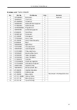
Summary of Contents for TAC-07HRA/E1

Page 1: ...O 28HA E1 TAC 07HRA EW TAC 07HA EW TAC 09HRA EW TAC 09HA EW TAC 12HRA EW TAC 12HA EW TAC 18HRA EW TAC 18HA EW TAC 09HRA ES TACO 09HA ES TAC 12HRA ES TACO 12HA ES TAC 36HRA WE TACO 36HA WE CONTENTS 1 IMPORTANT NOTICE 2 PRODUCT DIMENSIONS 3 REFRIGERATION CYCLE DIAGRAM 4 OPERATION DETAILS 5 WIRING DIAGRAM 6 EXPLOSION VIEW AND PART LISTS 7 PRECAUTION 8 NAMES OF PARTS 9 INSTALLATION 10 TROUBLE SHOOTING...

Page 2: ... for the interpretation of this information nor can it assume any liability in connection with its use The information specifications and parameters are subject to change due to technical modification or improvement without any prior notice The accurate specifications are presented on the nameplate label How to order spare parts To have your order filled promptly and correctly please furnish the f...

Page 3: ...32 375 276 256 52 55 TAC 09HRA ES 698 255 190 600 500 232 375 276 256 52 55 TAC 12HRA E1 777 250 205 700 552 256 439 2 302 277 8 48 55 TAC 12HRA EW 777 250 205 700 552 256 439 2 302 277 8 48 55 TAC 12HRA ES 777 250 205 700 552 256 439 2 302 277 8 48 55 TAC 18HRA E1 910 292 205 760 552 256 508 302 277 8 48 55 TAC 18HRA EW 910 292 205 760 552 256 508 302 277 8 48 55 TAC 24HRA E1 910 292 205 820 605 ...

Page 4: ...ry Compressor Accumulator Heat exchange condenser Heat exchange Evaporator 2 way valve Liquid side 3 way valve Gas side Cooling Heating Gas side 3 way valve Liquid side 2 way valve Heat exchange Evaporator Heat exchange condenser Accumulator Compressor 4 way valve Capillary Assembly Check valve ...

Page 5: ...Only then you CAN NOT preset the Heating operation with the remote controller 9 9 1 2 4 3 5 6 10 7 MODE button ECO button FAN SPEED button TEMP UP button TIMER button SLEEP button TEMP DOWN button To select the mode of operation In cooling mode press this button the temperature will increase 2 on the base of setting temperature In heating mode press this button the temperature will decrease 2 on t...

Page 6: ...able to retain and restore the original mode when being turned on or the power supply is resumed if the auto restart function activated power off after power on while if the auto restart function isn t activated the A C enters standby state Heat pump Mode Initial RT Initial ST Cooling RT 26 C 23 C Dry 26 C RT 20 C 7 C Heating RT 20 C 23 C Cooling only Mode Initial RT Initial ST Cooling RT 26 C 23 ...

Page 7: ... ST CRT 1 C the compressor is running b When ST CRT 1 C the compressor stops c When 1 C ST CRT 1 C the compressor keeps its original state 2 Outdoor fan motor and the compressor run simultaneously except for defrosting 3 The control of indoor fan motor a Indoor fan motor can operate by automatic low middle or high airflow speed circularly b Indoor fan motor automatic airflow speed control it works...

Page 8: ... Off Tim be in accord ing during d ing optiona m run into de 3 d c all require ax ᇞIPT 0min the co tion 1 the fir me should b is more than erature is le e set is 8 mi or is operatin on wind tem mpressor ope sting accordi Conditioner Se nomic opera ediately but ing Sleep F dance with o efrosting no l function st frosting onc ed to meet ompressor ru rst running ti be determine Figure 3 n or equal to...

Page 9: ...he machine runs into defrosting and last for 8 min if the accumulative totally less than 30min but accord with one of the condition option 1 3 then the machine runs into defrosting at the option 1 3 and the accumulative total time restarts from 0 Conditions for quitting defrosting 1 The quitting conditions for option 1 option 2 and 4 the machine quits from defrosting if any one below condition met...

Page 10: ...then no changed anymore 3 The machine will automatically shut up after running 10 hours under sleep mode When Timer ON and Sleep mode are implemented at the same time the Sleep mode can not be functioned 7 Timer function The timer can preset between 10min to 24h when the time set less than 10 hours the displayed time shown by 0 5 hour as the unit when the time set more than or equal to 10 hours th...

Page 11: ...ection the compressor can t start up until it stops 3 min later except for the defrosting process c After the compressor started it s operation state remains the same within 3 min even when ST RT variation 2 Anti frosting protection of indoor evaporator Cooling mode If IPT 0 C detected in consecutive 3 min compressor and outdoor fan motor to be stopped operation indoor fan motor runs at high speed...

Page 12: ... at the same time then failure codes appears by turns every eight seconds correspondingly 6a Sensor s failure protection when the sensor tested temperature out of the range 50 C T 110 C sensor failure is determined Once RT and or IPT sensor failure appears the compressor stops and indoor and outdoor fan motors shut off Remote controller doesn t response to any signal except for shutdown During fai...

Page 13: ...07HRA E1 TAC 09HRA E1 TACO 09HRA E1 TAC 12HRA E1 TACO 12HRA E1 TAC 18HRA E1 TACO 18HRA E1 TAC 24HRA E1 TACO 24HRA E1 TAC 09HRA ES TACO 09HRA ES TAC 12HRA ES TACO 12HRA ES TAC 09HRA EW TACO 09HRA EW TAC 12HRA EW TACO 09HRA EW TAC 18HRA EW TACO 09HRA EW INDOOR UNIT OUTDOOR UNIT ...

Page 14: ...Air Conditioner Service Manual 13 MODEL TAC 28HRA E1 TACO 28HRA E1 INDOOR UNIT OUTDOOR UNIT ...

Page 15: ...Air Conditioner Service Manual 14 MODEL TAC 36HRA WE TACO 36HA WE INDOOR UNIT OUTDOOR UNIT ...

Page 16: ...rvice Manual 15 6 Explosion view and parts Mode TAC 07HRA E1 TAC 09HRA E1 TAC 12HRA E1 TAC 18HRA E1 TAC 24HRA E1 TAC 09HRA ES TAC 12HRA ES INDOOR UNIT 22 23 25 19 18 17 16 15 14 13 12 11 10 9 8 7 6 5 4 3 2 1 24 20 26 21 ...

Page 17: ... 210901127S Display PCB 1 13 210746847B Front Panel 1 14 1170120044 Power Supply Cord 1 15 210738393 Electrical Box Cover 1 16 210900478A Terminal 1 17 210736832 Cable Clamp 1 18 210901224 Transformer 1 19 210901617N Main PCB 1 20 210736831 Electrical Box 1 21 210900333 Indoor Sensor Assembly 1 22 1170030047F Indoor Motor 1 23 210737653 Indoor Motor Cover 1 24 210737091 Drainage Hose 1 25 11700200...

Page 18: ...1127S Display PCB 1 12 210746847B Front Panel 1 13 1170120044 Power Supply Cord 1 15 210738393 Electrical Box Cover 1 16 210900478A Terminal 1 16 210736832 Cable Clamp 1 22 210901224 Transformer 1 17 210901617N Main PCB 1 18 210736831 Electrical Box 1 23 210900333 Indoor Sensor Assembly 1 20 1170030047F Indoor Motor 1 21 210737653 Indoor Motor Cover 1 15 210737091 Drainage Hose 1 19 1170020011 Van...

Page 19: ...1127S Display PCB 1 13 210746792C Front Panel 1 14 1170120045 Power Supply Cord 1 15 210737654 Electrical Box Cover 1 16 210900376 Terminal 1 17 210736832 Cable Clamp 1 18 210901510 Transformer 1 19 210901526AN Main PCB 1 20 210736831 Electrical Box 1 21 210900333 Indoor Sensor Assembly 1 22 1170030047F Indoor Motor 1 23 210737653 Indoor Motor Cover 1 24 210737091 Drainage Hose 1 25 1170020011 Van...

Page 20: ...01127S Display PCB 1 13 210746767C Front Panel 1 14 1170120045 Power Supply Cord 1 15 210738393 Electrical Box Cover 1 16 210900376 Terminal 1 17 210736832 Cable Clamp 1 18 210901224 Transformer 1 19 210901617T Main PCB 1 20 210736831 Electrical Box 1 21 210900333 Indoor Sensor Assembly 1 22 1170030067J Indoor Motor 1 23 210738581 Indoor Motor Cover 1 24 210737091 Drainage Hose 1 25 1170020031AC V...

Page 21: ...01127S Display PCB 1 13 210746767C Front Panel 1 14 1170120045 Power Supply Cord 1 15 210738393 Electrical Box Cover 1 16 210900376 Terminal 1 17 210736832 Cable Clamp 1 18 210901224 Transformer 1 19 210901617AJ Main PCB 1 20 210736831 Electrical Box 1 21 210900333 Indoor Sensor Assembly 1 22 1170030101B Indoor Motor 1 23 210738581 Indoor Motor Cover 1 24 210737091 Drainage Hose 1 25 1170020031AC ...

Page 22: ...0901127S Display PCB 1 12 210739720B Front Panel 1 13 1170120044 Power Supply Cord 1 15 210738393 Electrical Box Cover 1 16 210900478A Terminal 1 16 210736832 Cable Clamp 1 22 210901224 Transformer 1 17 210901617N Main PCB 1 18 210736831 Electrical Box 1 23 210900333 Indoor Sensor Assembly 1 20 1170030047F Indoor Motor 1 21 210737653 Indoor Motor Cover 1 15 210737091 Drainage Hose 1 19 1170020011 ...

Page 23: ...901127S Display PCB 1 13 210739715D Front Panel 1 14 1170120045 Power Supply Cord 1 15 210737654 Electrical Box Cover 1 16 210900376 Terminal 1 17 210736832 Cable Clamp 1 18 210901510 Transformer 1 19 210901526AN Main PCB 1 20 210736831 Electrical Box 1 21 210900333 Indoor Sensor Assembly 1 22 1170030047F Indoor Motor 1 23 210737653 Indoor Motor Cover 1 24 210737091 Drainage Hose 1 25 1170020011 V...

Page 24: ...Air Conditioner Service Manual 23 Mode TAC 07HRA EW TAC 09HRA EW TAC 12HRA EW TAC 18HRA EW INDOOR UNIT 21 22 20 19 18 14 13 12 11 10 9 8 7 6 5 4 3 2 1 23 24 25 29 30 31 16 17 26 27 28 15 ...

Page 25: ...nt Panel 1 15 210738624A Display PCB Cover 1 16 1170120044 Power Supply Cord 1 17 210738393 Electrical Box Cover 1 18 210736832 Cable Clamp 1 19 210900376 Terminal 1 20 210901224 Transformer 1 21 210901617N Main PCB 1 22 210736831 Electrical Box 1 23 210900333 Indoor Sensor Assembly 1 24 1170030047F Indoor Motor 1 25 210737653 Indoor Motor Cover 1 26 210701902 Step Motor connector 1 27 210900129 S...

Page 26: ...l 1 15 210738208C Display PCB Cover 1 16 1170120045 Power Supply Cord 1 17 210737654 Electrical Box Cover 1 18 210736832 Cable Clamp 1 19 210900376 Terminal 1 20 210901224 Transformer 1 21 210901617AS Main PCB 1 22 210736831 Electrical Box 1 23 210900333 Indoor Sensor Assembly 1 24 1170030047F Indoor Motor 1 25 210737653 Indoor Motor Cover 1 26 210701902 Step Motor connector 1 27 210900129 Step Mo...

Page 27: ...38571A Front Panel 1 15 210738624A Display PCB Cover 1 16 210738393 Electrical Box Cover 1 17 210736832 Cable Clamp 1 18 210900376 Terminal 1 19 210901224 Transformer 1 20 210901617T Main PCB 1 21 210736831 Electrical Box 1 22 1170030067J Indoor Motor 1 23 210738581 Indoor Motor Cover 1 24 210701902 Step Motor connector 1 25 210900129 Step Motor 1 26 210701906 Step Motor Supporter 1 27 210737091 D...

Page 28: ...Air Conditioner Service Manual 27 Mode TAC 28HRIA E1 INDOOR UNIT 19 20 18 17 16 14 13 12 11 10 9 8 7 6 5 4 3 2 1 21 22 23 24 25 26 15 ...

Page 29: ... Box 1 13 210901127S Display PCB 1 14 210746772B Front Panel 1 15 210738393 Electrical Box Cover 1 16 210900380 Terminal 1 17 210736912 Cable Clamp 1 18 210901224 Transformer 1 19 210901617Z Main PCB 1 20 210736831 Electrical Box 1 21 210900333 Indoor Sensor Assembly 1 22 210900087AH Indoor Motor 1 23 210738388 Indoor Motor Cover 1 24 210737091 Drainage Hose 1 25 1170020031AC Vane Motor 1 26 21073...

Page 30: ...Air Conditioner Service Manual 29 Mode TAC 36HRA WE INDOOR UNIT 1 2 3 4 5 6 7 8 9 10 11 12 13 14 15 16 17 18 19 20 21 22 23 24 25 26 27 28 29 30 32 33 34 31 ...

Page 31: ... 16 1070252211 Display PCB Box 1 17 210900913D Display PCB 1 18 210736370 Front Panel 1 19 210736088 Display PCB 1 20 210735782 Terminal Cover 1 21 210800423 Terminal fixing board 1 22 210900380 Terminal 1 23 1070451081AB Cable Clamp 1 24 210703528 Electrical Box 1 25 210901109 Main PCB 1 26 210900333 Indoor Sensor Assembly 1 27 210701933 Vertical Vane Connector 2 28 210900522A Step Motor 1 29 210...

Page 32: ...e Manual 31 MODEL TACO 07HRA E1 TACO 09HRA E1 TACO 12HRA E1 TACO 18HRA E1 TACO 24HRA E1 TACO 07HA E2 TACO 09HA E2 TACO 12HA E2 TACO 18HA E2 OUTDOOR UNIT 11 20 19 7 6 5 18 14 15 17 16 21 22 24 23 25 12 13 9 10 8 4 3 2 26 1 27 ...

Page 33: ...38951 4 way Valve Assembly 1 13 210837829 Base 1 14 1081990012 Right Plate 1 15 211236491 Two way Valve 1 16 1081990013 Valve Supporter 1 17 1120130039 Three way Valve 1 18 1073521301 Electrical Box Cover 1 19 1070040001 Cable Clamp φ6 1 20 1070040002 Cable Clamp φ7 1 21 1170500131 Terminal 1 22 1170100031 Fan Motor Capacitor 1 23 1170100014A Compressor Capacitor 1 24 1080010002 Capacitor Strip 1 ...

Page 34: ...8962 4 way Valve Assembly 1 13 210800528 Base 1 14 1081990012 Right Plate 1 15 211236491 Two way Valve 1 16 1081990013 Valve Supporter 1 17 1120130039 Three way Valve 1 18 1073521301 Electrical Box Cover 1 19 1070040001 Cable Clamp φ6 1 20 1070040002 Cable Clamp φ7 1 21 1170500131 Terminal 1 22 1170100031 Fan Motor Capacitor 1 23 1170100014A Compressor Capacitor 1 24 1080010002 Capacitor Strip 1 2...

Page 35: ...Valve Assembly 1 13 210800466 Base 1 14 1080050002 Right Plate 1 15 1120120021 Two way Valve 1 16 1080050003 Valve Supporter 1 17 211206766 Three way Valve 1 18 1070350971 Electrical Box Cover 1 19 1070040001 Cable Clamp φ6 1 20 1070040002 Cable Clamp φ7 1 21 1170500131 Terminal 1 22 1170100010AB Fan Motor Capacitor 1 23 1170100004A Compressor Capacitor 1 24 1080010006 Capacitor Strip 1 25 1081990...

Page 36: ...11238305 4 way Valve Assembly 1 13 210800487 Base 1 14 1080050002 Right Plate 1 15 1120120021 Two way Valve 1 16 1080050003 Valve Supporter 1 17 1120130085 Three way Valve 1 18 1070350971 Electrical Box Cover 1 19 1070040001 Cable Clamp φ6 1 20 1070040003 Cable Clamp φ8 1 21 1170500131 Terminal 1 22 1170100027A Fan Motor Capacitor 1 23 1170100004A Compressor Capacitor 1 24 1080010006 Capacitor Str...

Page 37: ...ay Valve Assembly 1 13 210800568 Base 1 14 1081990054 Right Plate 1 15 1120120021 Two way Valve 1 16 1081990055 Valve Supporter 1 17 1120130037 Three way Valve 1 18 1070350971 Electrical Box Cover 1 19 1070040001 Cable Clampφ6 1 20 1070040008 Cable Clampφ10 1 21 1170500131 Terminal 1 22 1170100030A Fan Motor Capacitor 1 23 1170100033A Compressor Capacitor 1 24 1080010006 Capacitor Strip 1 25 10819...

Page 38: ... Valve Assembly 1 13 210837829 Base 1 14 1081990012 Right Plate 1 15 211236491 Two way Valve 1 16 1081990013 Valve Supporter 1 17 1120130039 Three way Valve 1 18 1073521301 Electrical Box Cover 1 19 1070040001 Cable Clamp φ6 1 20 1070040002 Cable Clamp φ7 1 21 1170500131 Terminal 1 22 1170100031A Fan Motor Capacitor 1 23 1170100014A Compressor Capacitor 1 24 1080010002 Capacitor Strip 1 25 1081990...

Page 39: ... Valve Assembly 1 13 210800528 Base 1 14 1081990012 Right Plate 1 15 211236491 Two way Valve 1 16 1081990013 Valve Supporter 1 17 1120130039 Three way Valve 1 18 1073521301 Electrical Box Cover 1 19 1070040001 Cable Clamp φ6 1 20 1070040002 Cable Clamp φ7 1 21 1170500131 Terminal 1 22 1170100031 Fan Motor Capacitor 1 23 1170100014A Compressor Capacitor 1 24 1080010002 Capacitor Strip 1 25 10819900...

Page 40: ...Valve Assembly 1 13 210800466 Base 1 14 1080050002 Right Plate 1 15 1120120021 Two way Valve 1 16 1080050003 Valve Supporter 1 17 211206766 Three way Valve 1 18 1070350971 Electrical Box Cover 1 19 1070040001 Cable Clamp φ6 1 20 1070040002 Cable Clamp φ7 1 21 1170500131 Terminal 1 22 1170100010AB Fan Motor Capacitor 1 23 1170100004A Compressor Capacitor 1 24 1080010006 Capacitor Strip 1 25 1081990...

Page 41: ...Valve Assembly 1 13 210800487 Base 1 14 1080050002 Right Plate 1 15 1120120021 Two way Valve 1 16 1080050003 Valve Supporter 1 17 1120130085 Three way Valve 1 18 1070350971 Electrical Box Cover 1 19 1070040001 Cable Clamp φ6 1 20 1070040003 Cable Clamp φ8 1 21 1170500131 Terminal 1 22 1170100027A Fan Motor Capacitor 1 23 1170100004A Compressor Capacitor 1 24 1080010006 Capacitor Strip 1 25 1081990...

Page 42: ...Air Conditioner Service Manual 41 MODEL TACO 28HRA E1 TACO 36HA WE OUTDOOR UNIT 10 6 7 5 4 20 14 12 13 15 11 8 9 16 17 18 19 3 2 21 22 24 23 25 26 1 27 ...

Page 43: ...alve Assembly 1 13 1081990178 Base 1 14 1081990039 Right Plate 1 15 1120120021 Two way Valve 1 16 1081990041 Valve Supporter 1 17 1120130037 Three way Valve 1 18 1070350971 Electrical Box Cover 1 19 1074060118 Cable Clamp 1 20 1170200054 Terminal 1 21 1170100030A Fan Motor Capacitor 1 22 1170100025A Compressor Capacitor 1 23 1080010006 Capacitor Strip 1 24 1081990049 Electrical Parts Box 1 25 1174...

Page 44: ...Valve 1 12 211233791 4 way Valve Assembly 1 13 210826467 Base 1 14 1080050043 Right Plate 1 15 1120120033 Two way Valve 1 16 1080050044 Valve Supporter 1 17 1120130045 Three way Valve 1 18 1070350971 Electrical Box Cover 1 19 1074060118 Cable Clamp 1 20 1170200054 Terminal 1 21 1170100067A Fan Motor Capacitor 1 22 210901177 Compressor Capacitor 1 23 1080850106 Capacitor Strip 1 24 1080050056 Elect...

Page 45: ... accordance with the wiring rules z The air conditioner must be installed by professional or qualified persons Do not install the appliance at a distance of less than 50 cm from inflammable substances alcohol etc Or from pressurized containers e g spray cans z If the appliance is used in areas without the possibility of ventilation precautions must be taken to prevent any leaks of refrigerant gas ...

Page 46: ...ilures z The user is responsible for having the appliance installed by a qualified technician who must check that it is earthed in accordance with current legislation and insert a thermomagnetic circuit breaker z The batteries in remote controller must be recycled or disposed of properly Disposal of Scrap Batteries Please discard the batteries as sorted municipal waste at the accessible collection...

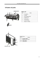
Page 47: ...el 2 Air filter 3 Special filter option 4 Display PCB 5 Vertical vane 6 Horizontal vane 7 Remote controller 8 Names of parts Outdoor unit No Name 8 Air outlet grille 9 Electronic box cover 10 2 way valve 11 3 way valve 1 2 3 4 6 5 7 INDOOR UNIT 8 9 10 11 OUTDOOR UNIT ...

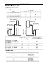
Page 48: ...A 5m TAC 07HRA E1 TAC 09HRA E1 TAC 07HRA EW TAC 09HRA EW TAC 09HRA ES 3 0 20 20g m TAC 12HRA E1 TAC 12HRA EW TAC 12HRA ES 3 5 20 20g m TAC 18HRA E1 TAC 12HRA EW 5 0 20 30g m TAC 24HRA E1 TAC 28HRA E1 5 0 20 30g m TAC 36HRA WE 5 0 20 40g m Connecting cables The power cord should be selected according to the following specifications sheet Appliance Amps Wire Size 5 AWG21 0 75 mm2 10 AWG18 1 0 mm2 13...

Page 49: ... as shown in the picture z Install the indoor unit where the filter can be easily accessible OUTDOOR UNIT z Do not install the outdoor unit near sources of heat steam or flammable gas z Do not install the unit in too windy or dusty places z Do not install the unit where people often pass Select a place where the air discharge and operating sound level will not disturb the neighbors z Avoid install...

Page 50: ...ll the hole in the wall for the piping if necessary according to the position of the mounting plate 2 Install a flexible flange through the hole in the wall to keep the latter intact and clean The hole must slope downwards towards the exterior Note Keep the drain pipe down towards the direction of the wall hole otherwise leakage may occur 9 2 3Electrical connections Indoor unit 1 Lift the front pa...

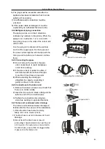
Page 51: ...ipe is bent or pulled too often it will become stiff Do not bend the pipe more than three times at one point z When extending the rolled pipe straighten the pipe by unwinding it gently as shown in the picture 9 2 6 Connections to the indoor unit 1 Remove the indoor unit pipe cap check that there is no debris inside 2 Insert the fare nut and create a flange at the extreme end of the connection pipe...

Page 52: ...htening procedures described for the indoor unit Note If the tightening torque is not sufficient there will probably be some leakage With excessive tightening torque there will also be some leakage as the flange could be damaged 9 2 6Bleeding Air and humidity left inside the refrigerant circuit can cause compressor malfunction After having connected the indoor and outdoor units bleed the air and h...

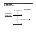
Page 53: ...t does not operate at all Power supply voltage check Connector contact check Power trans output voltage PCB assembly check Power receptable voltage Product input voltage PCB assembly Power input voltage Driving load terminal Display PCB connector AC about 12 3V 52 ...

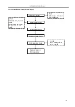
Page 54: ...ontact Motor related parts Motor detail check Operation mode check PCB assembly check Check Motor driving circuit Relay output Check Motor output connector Motor capacitor Check Motor bearing inserted state Fan Blower fixed state Fan Blower contact state Replace motor or PCB assembly 53 ...

Page 55: ...ature sensor open short check Thermistor and evaporator surface contact check Clearance is needed 5mm Connector check Contact power Connector check Contact power Disconnection short circuit check of connecting wire OLP High pressure switch Low pressure switch check Electric wire connection check for outdoor side Operation mode dehumidifying check Compressor motor detail check PCB assembly check Ch...

Page 56: ...hort circuit mal connection Vane motor check PCB assembly check vane motor driving circuit Replace the vane motor Replace the PCB Heating operation ON by remote controller Connector check If the 4 way valve is ON tick sounds PCB assembly 4 way valve connection check outdoor unit connecting wire check Check the voltage of 4 way valve coil 4 way valve coil resistance check 55 ...

Page 57: ...n 2 Room temperature sensor IRT and Indoor pipe coil temperature sensor IPT damage short or broken Solution check the resistance of the sensor R 25 5 kΩ if short or broken please replace it 3 The PCB fail Solution Replace the indoor main PCB 11 5 2 Display E6 Reasons 1 The indoor motor connection terminal loose or not plugged in Solution Check the connecter of indoor motor and slot CN3 and CN4 if ...

Page 58: ...TCL Air Conditioner Service Manual 57 2 The indoor motor damage Solution Check and replace the motor 3 The indoor main PCB damage Solution Replace the indoor main PCB ...

Page 59: ...1 3 981 2 192 76 0 895 0 746 13 26 239 4 186 32 3 836 2 146 77 0 869 0 728 12 24 984 4 152 33 3 697 2 101 78 0 843 0 710 11 23 795 4 117 34 3 563 2 057 79 0 819 0 692 10 22 671 4 082 35 3 435 2 012 80 0 795 0 675 9 21 606 4 045 36 3 313 1 969 81 0 773 0 658 8 20 598 4 008 37 3 195 1 926 82 0 751 0 641 7 19 644 3 969 38 3 082 1 883 83 0 729 0 625 6 18 732 3 930 39 2 974 1 842 84 0 709 0 610 5 17 88...

Page 60: ...Resistance at 25 5 kΩ TH1 indoor room temperature sensor and outside air temperature sensor TH2 indoor exchange temperature sensor and outside exchange temperature sensor Before measuring resistance disconnect connectors as shown above ...

Reviews: