
3
SAFETY & PRECAUTIONS
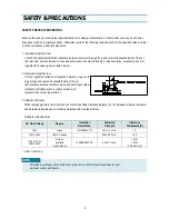
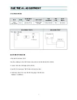
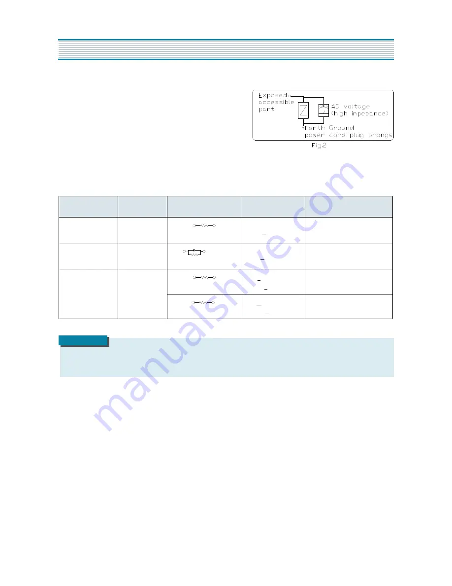
4. Leakage current test
Confirm specified or lower leakage current between B(earth
ground, power cord plug prongs) and externally exposed accessi-
ble parts (RF terminals, antenna terminals, video and audio input
output terminals, microphone jacks, earphone jacks, etc.)
Measuring method:(Power ON) Insert load Z between B(earth
ground, power cord plug prongs) and exposed accessible parts.
Use on AC voltmeter to measure across both terminals of load Z.
See figure2 and following table.
Leakage current ratings for selected are as
AC Line Voltage
Region
Load Z
Leakage Cur-
rent(
i
)
Clearance Distance(d),(d’)
100V
Japan
1k
Ω
i
<
1 mArms
Exposed accessible parts
110 to 130V
USA &Canada
15kmF
1k
Ω
i
<
0.5mArms
Exposed accessible parts
110 to 130V
200 to 240V
Europe
Australia
2k
Ω
i
<
0.7mA peak
i
<
2mAdc
Antenna earth terminals
50k
Ω
i
<
0.7mA peak
i
<
1mAdc
Other terminals
This table is unofficial and for reference only. Be sure to confirm the precise values
for your particular country and locality.
NOTE
Summary of Contents for ST263 DVST7L3
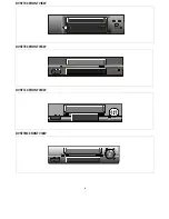
Page 4: ...4 DVST7C3 FRONT VIEW DVST7E3 FRONT VIEW DVST7L3 FRONT VIEW DVST7M3 FRONT VIEW ...
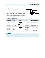
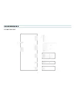
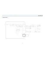
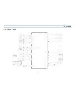
Page 8: ...9 CIRCUIT INFORMATION 1 INTERCONNECT WIRING DIAGRAM ...
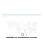
Page 9: ...10 CIRCUIT INFORMATION 2 POWER CIRCUIT DIAGRAM ...
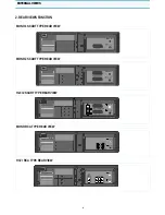
Page 11: ...12 CIRCUIT INFORMATION 3 POWER BLOCK DIAGRAM ...
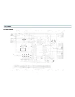
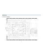
Page 12: ...13 CIRCUIT INFORMATION 4 SYSCON CIRCUIT DIAGRAM ...
Page 14: ...15 CIRCUIT INFORMATION 5 SERVO SYSCON BLOCK DIAGRAM ...
Page 15: ...16 CIRCUIT INFORMATION 6 AV SECAM COLOR CIRCUIT DIAGRAM ...
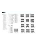
Page 17: ...18 CIRCUIT INFORMATION 7 1 VIDEO PLAYBACK PATH FOR PAL 7 2 VIDEO RECORD PATH FOR PAL ...
Page 18: ...19 CIRCUIT INFORMATION 8 HIFI SW CIRCUIT DIAGRAM ...
Page 20: ...21 CIRCUIT INFORMATION 9 PIF CIRCUIT DIAGRAM ...
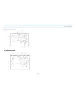
Page 22: ...24 DISASSEMBLY 1 PACKING ASS Y ...
Page 23: ...26 DVST7L3 SERIES ...
Page 24: ...29 DISASSEMBLY 3 INSTRUMENT DISASSEMBLY 3 1 SET TOTAL ...


