S0302000
Page 7
General Maintenance Procedures
Return to Master Table of Contents
NOTE:
Grease lip seals before
assembly.
CLEANING AND INSPECTION
GENERAL GUIDELINES
All parts must be clean to permit an effective inspection. During assembly, it is very important that no dirt or
foreign material enters unit being assembled. Even minute particles can cause malfunction of close fitting
parts such as thrust bearing, matched parts, etc.
1.
Clean all metal parts thoroughly using a suitable cleaning fluid. It is recommended that parts be
immersed in cleaning fluid and moved up and down slowly until all oils, lubricants, and/or foreign
materials are dissolved and parts are thoroughly clean.
2.
For bearings that can be removed, soak them in a suitable cleaning fluid for a minute or two, then
remove bearings from cleaning fluid and strike flat against a block of wood to dislodge solidified
particles of lubricant. Immerse again in cleaning fluid to flush out particles. Repeat above operation
until bearings are thoroughly clean. To dry bearings, use moisture-free compressed air. Be careful to
direct air stream across bearing to avoid spinning bearings that are not lubricated. DO NOT SPIN
BEARINGS WHEN DRYING; bearings may be rotated slowly by hand to facilitate drying process.
3.
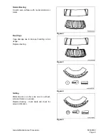
Carefully inspect all bearing rollers, cages and cups for wear, chipping or nicks to determine
condition. Do not replace a bearing cone or cup individually without replacing mating cup or cone at
the same time. After inspection, dip bearings in light weight oil and wrap in clean lintless cloth or
paper to protect them until installation.
For those bearings that are to be inspected in place; inspect bearings for roughness of rotation,
scoring, pitting, cracked or chipped races. If any of these defects are found, replace bearings. Also
inspect defective bearing housing and/or shaft for grooved, galled or burred conditions that indicate
bearing has been turning in its housing or on its shaft.
4.
It is more economical to replace oil seals, O-rings, sealing rings, gaskets and snap rings when unit is
disassembled than waiting for premature failures; refer to latest Micro Fiche and/or Parts Book for
replacement items. Be extremely careful when installing sealing members, to avoid cutting or
WARNING!
Care should be exercised to avoid inhalation of vapors, exposure to skin and creating fire
hazards when using solvent type cleaners.
Figure 1
Summary of Contents for Solar 470LC-V
Page 2: ......
Page 4: ......
Page 7: ...1SAFETY...
Page 8: ......
Page 46: ...S0102000 Page 38 Track Excavator Safety...
Page 47: ...1SPECIFICATIONS...
Page 48: ......
Page 54: ...S0202090K Page 6 Specifications for Solar 470LC V...
Page 70: ...S0202090K Page 22 Specifications for Solar 470LC V...
Page 71: ...1GENERAL MAINTENANCE...
Page 72: ......
Page 86: ...S0302000 Page 14 General Maintenance Procedures Return to Master Table of Contents...
Page 99: ...1UPPER STRUCTURE...
Page 100: ......
Page 102: ...S0402040K Page 2 Cab TABLE OF CONTENTS Removal 3 Installation 6...
Page 116: ...S0403050K Page 8 Counterweight Return to Master Table of Contents...
Page 140: ...S0407000 Page 6 Swing Bearing...
Page 155: ...S0408060 Page 15 Swing Reduction Gearbox...
Page 163: ...1LOWER STRUCTURE AND CHASSIS...
Page 164: ......
Page 190: ...S0505120 Page 26 Track Assembly Return to Master Table of Contents...
Page 191: ...1ENGINE AND DRIVE TRAIN...
Page 192: ......
Page 203: ...S0605060K Page 11 Air Conditioner Face and Defroster ARS1300L Figure 12...
Page 218: ...S0605060K Page 26 Air Conditioner...
Page 227: ...1HYDRAULICS...
Page 228: ......
Page 258: ...S0702190K Page 30 Hydraulic System Troubleshooting Testing and Adjustment...
Page 260: ...S0703010K Page 2 Accumulator TABLE OF CONTENTS General Description 3 Specifications 4...
Page 264: ...S0703010K Page 6 Accumulator...
Page 272: ...S0704090K Page 8 Center Joint Swivel...
Page 281: ...S0705000 Page 9 Cylinders...
Page 285: ...S0705000 Page 13 Cylinders...
Page 289: ...S0705000 Page 17 Cylinders...
Page 297: ...S0705000 Page 25 Cylinders...
Page 306: ...S0705000 Page 34 Cylinders 17 Force out pin bushing 1 from body of cylinder Figure 28...
Page 310: ...S0705000 Page 38 Cylinders...
Page 317: ...S0707260 Page 7 Swing Motor...
Page 321: ...S0707260 Page 11 Swing Motor SPECIAL TOOLS Figure 5...
Page 338: ...S0707260 Page 28 Swing Motor...
Page 350: ...S0707365 Page 12 Travel Motor With Gearbox A6V160HD PARTS LIST Travel Motor Figure 12 HTS6331...
Page 354: ...S0707365 Page 16 Travel Motor With Gearbox A6V160HD Travel Motor Control HTS6331 Figure 14...
Page 383: ...S0707365 Page 45 Travel Motor With Gearbox A6V160HD 29 Remove gasket Figure 91 Figure 91 3061...
Page 401: ...S0708325K Page 3 Main Pump Rexroth...
Page 402: ...S0708325K Page 4 Main Pump Rexroth SECTIONAL VIEW A8VO200LA1KH1 63 ASS0010L Figure 1...
Page 403: ...S0708325K Page 5 Main Pump Rexroth ASS0020L Figure 2...
Page 414: ...S0708325K Page 16 Main Pump Rexroth REMOVE THE CONTROL HOUSING ASS0280L Figure 29...
Page 450: ...S0708325K Page 52 Main Pump Rexroth INSTALLATION OF COVER AUXILIARY DRIVE ASS1100L Figure 111...
Page 454: ...S0708325K Page 56 Main Pump Rexroth...
Page 459: ...S0709402K Page 5 Control Valve Kayaba Model KVMG 400 DA...
Page 461: ...S0709402K Page 7 Control Valve Kayaba Model KVMG 400 DA Figure 1...
Page 463: ...S0709402K Page 9 Control Valve Kayaba Model KVMG 400 DA Figure 2...
Page 465: ...S0709402K Page 11 Control Valve Kayaba Model KVMG 400 DA Figure 3...
Page 475: ...S0709402K Page 21 Control Valve Kayaba Model KVMG 400 DA...
Page 477: ...S0709402K Page 23 Control Valve Kayaba Model KVMG 400 DA Figure 13...
Page 483: ...S0709402K Page 29 Control Valve Kayaba Model KVMG 400 DA PARTS LIST Figure 30...
Page 484: ...S0709402K Page 30 Control Valve Kayaba Model KVMG 400 DA Figure 31...
Page 485: ...S0709402K Page 31 Control Valve Kayaba Model KVMG 400 DA Figure 32...
Page 509: ...S0709402K Page 55 Control Valve Kayaba Model KVMG 400 DA Figure 57 S N 1051 and Up...
Page 512: ...S0709402K Page 58 Control Valve Kayaba Model KVMG 400 DA...
Page 560: ...S0792170K Page 4 Hydraulic Schematic S470LC V SOLAR 470LC V Figure 2...
Page 561: ...S0792170K Page 5 Hydraulic Schematic S470LC V...
Page 562: ...S0792170K Page 6 Hydraulic Schematic S470LC V...
Page 563: ...1ELECTRICAL SYSTEM...
Page 564: ......
Page 618: ...S0802220K Page 54 Electrical System...
Page 637: ...S0802220K Page 73 Electrical System...
Page 644: ...S0892170K Page 4 Electrical Schematic S470LC V SOLAR 470LC V Figure 2...
Page 646: ...S0892170K Page 6 Electrical Schematic S470LC V...
Page 647: ...1ATTACHMENTS...
Page 648: ......
Page 668: ......

