Page 5
Return to Master Table of Contents
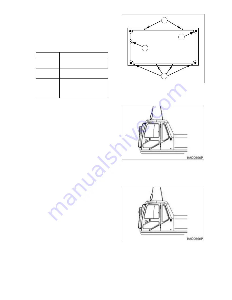
17. Remove f our m ounting nuts fr om f our
corners of cabin floor (2, Figure 4).
18. Remove four hex bol ts (3, Fig ure 4) from
door side of cabin floor.
19. Remove two h ex bol ts ( 1, Figure 4) fr om
right s ide of cabin floor an d one bo lt ( 4)
under front window of cab floor.
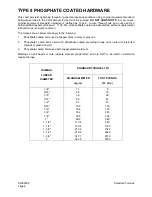
20. Using a suitable lifting device, attach slings
to four lift points on top of cab (Figure 5).
NOTE:
Cab weig hs approximately 290
kg (639 lb).
21. Lift ca b fr om 2 5 - 5 0 mm ( 1" - 2") above
deck hei ght. Chec k tha t all el ectrical
connections have bee n dis connected an d
all other items unbolted.
22. Continue lifting with the as sist cr ane to
remove the cab shell. Lower the shell to a
pre-prepared safe blocking support.
INSTALLATION
1.
Using a suitable lifting device, attach slings
to four lift points on top of cab (Figure 5).
NOTE:
Cab weig hs approximately 290
kg (639 lb).
2.
Lower cab into position on cab floor
Quantity
Description
4
16 mm hex nuts at each
corner of the cab
4
10 mm x 1.5 hex bolts at
the door side of the cab
3
10 mm x 1.5 mm hex
head bolts, 2 on the right
side of the cab and 1
under the front window.
HAOF270L
2
1
3
4
Figure 4
Figure 5
Figure 6
Summary of Contents for Solar 200W-V
Page 1: ...Shop Manual 2023 7139E Serial Number 0001 and Up March 2000 Solar 200W V...
Page 3: ......
Page 6: ...Return to Master Table of Contents 1SAFETY...
Page 28: ...S0102020 Page 22 Wheel Excavator Safety Return to Master Table of Contents...
Page 29: ...Return to Master Table of Contents 1SPECIFICATIONS...
Page 30: ...Return to Master Table of Contents...
Page 37: ...S0202040 Page 7 Specifications for Solar 200W V Return to Master Table of Contents...
Page 57: ...Return to Master Table of Contents 1GENERAL MAINTENANCE...
Page 58: ...Return to Master Table of Contents...
Page 72: ...S0302000 Page 14 General Maintenance Procedures Return to Master Table of Contents...
Page 85: ...Return to Master Table of Contents 1UPPER STRUCTURE...


