-3-
DVD
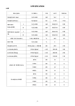
Description
Condition
Unit
Limit
Nominal
Video Signal Level
Vp-p
0.7
±
0.1
0.7
SYNC Level
Vp-p
0.3
±
0.1
0.3
Video out level
75% color bar/75ohm
Vp-p
1.0
±
0.2
1
Video out level(Unload)
75% color bar
Vp-p
2.0
±
0.2
2
CD
1kHz/0dB/10K
V
0.6
±
0.2
0.7
Audio out level
DVD
1kHz/0dB/10K
V
2+0/-0.6
1.5
LINE OUT LEVEL
1kHz/0dB/10K
V
≥
2.8
3.6
20Hz
dB
≤±
3
0
125Hz
dB
≤±
3
0
10kHz
dB
≤±
3
0
FREQ RESP (DVD)
(20Hz~20kHz)
20kHz
dB
≤±
3
0
Signal-to-noise radio
Infinity zere/-
dB/L&R
∝
dB
≥
60
≥
60
Audio distortion&noise (DVD)
1kHz/0dB/L&R
dB
≤
-65
-65
Dynamic range (DVD)
1kHz/-60dB
dB
≥
85
≥
85
R/L Cross sound (DVD)
1kHz/0dB/L&R
dB
≥
45
≥
45
1kHz Channel unbalance
1kHz/0dB/L&R
dB
≤
3
0
Power Consumption
Standby
W
≤
1
≤
1
DC 9V
Rating
W
≤
12
≤
12
ECC Entircity
A BEX TDV-552
um
≥
100
100
Scratch
A BEX TDV-541
mm
≥
1.6
1.6
Black dot
A BEX TDV-545
mm
≥ф
0.8
0.8
Finger Print
A BEX TDV-545
um
≥ф
65
65
Vertical deviation
A BEX TDV-533
mm
≥
0.6
0.6
Note:
Nominal specs represent the design specs. All units should be able to approximate these. Some will exceed
and some may drop slightly below these specs. Limit specs represent the absolute worst condition that might still
be considered acceptable. In no case should a unit fail to meet limit specs.
Summary of Contents for OSDPC78001
Page 1: ...7 Inch LCD Color Monitor DVD Player DEC 2006 DPC 7800NT 2708ED OSDPC78001...
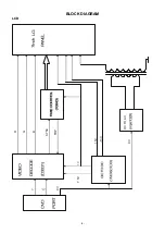
Page 5: ...4 BLOCK DIAGRAM LCD 15V 13V G B 9V Y 9V SYNC FRP 5V R 7 5V DC TO AC...
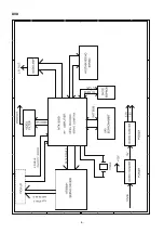
Page 6: ...5 DVD 5 5 4 4 3 3 2 2 1 1 D D C C B B A A US TRACK SLED DRIVER FE TE DRIVER SPINDLE...
Page 10: ...9 PRINTED CIRCUIT BOARD Monitor Main PCB Top View Bottom View...
Page 11: ...10 Charger Circuit PCB Top View Bottom View...
Page 12: ...11 DVD KEY PCB 1 DVD KEY PCB 2...
Page 13: ...12 DVD Main PCB TOP View...
Page 14: ...13 DVD Main PCB Bottom View...
Page 17: ...16 IC BLOCK DIAGRAM DESCRIPTION Q10 SS9969...
Page 22: ...21 IC BLOCK DIAGRAM DESCRIPTION ICP1 EL7630 Pin Name 1 LX 2 GND 3 FB 4 ENAB 5 VIN...
Page 25: ...24 IC BLOCK DIAGRAM DESCRIPTION DVD T2 M12L64164A...
Page 26: ...25 IC BLOCK DIAGRAM DESCRIPTION T2 M12L64164A...
Page 29: ...28 IC BLOCK DIAGRAM DESCRIPTION T4 S29AL008D...
Page 30: ...29 IC BLOCK DIAGRAM DESCRIPTION T4 S29AL008D...
Page 31: ...30 IC BLOCK DIAGRAM DESCRIPTION U1 S8521...
Page 33: ...32 EXPLODED VIEW...
Page 44: ...MEMO...


