28
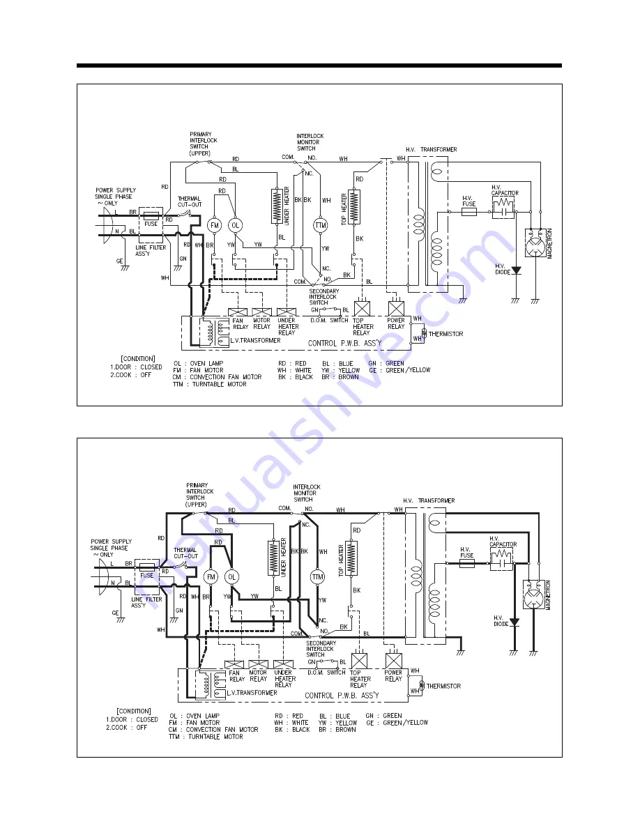
IDLE CONDITION
MICROWAVE COOKING CONDITION
SCHEMATIC DIAGRAM
Page 1: ...ICS CO LTD S M No C870T0S003 Caution In this Manual some parts can be changed for improving their performance without notice in the parts list So if you need the latest parts information please refer...
Page 2: ...proper alignment integrity and connections d Any defective or misadjusted components in the interlock monitor door seal and microwave generation and transmission systems shall be repaired replaced or...
Page 3: ...The oven should be placed as far from high temperature source and vapour as possible 3 The power supply cord is about 1 1m 3 6ft long Earthing is required when connecting the power source 4 Maximum po...
Page 4: ...X 398 X 320 mm 19 7 X 15 7 X 12 6 in CAVITY DIMENSIONS W X D X H 310 X 310 X 229 mm 12 2 X 12 6 X 9 0 in NET WEIGHT 17 6 kg 38 9 Ibs TIMER 60 minutes SELECT FUNCTION Microwave Grill Convection Combin...
Page 5: ...magnetron tube will immediately stop operating 3 DOOR SCREEN Allows viewing of food Microwave cannot pass through perforations in screen 4 GRILL HEATER Turns on when grill and simulta neous cooking i...
Page 6: ...be ready to operate dial knob Dial Knob Used to set the cooking time time of day and weight input When blinking the oven is operating in GRILL When blinking the onve is operating in MICROWAVE COOK Whe...
Page 7: ...ruction except clock 2 Open the door You can restart the oven by closing the door and touching button ERASING INSTRUCTIONS Touch STOP CLEAR button to erase all instructions you set previously Opening...
Page 8: ...the leakage of microwave 1 Primary interlock switch When the door is closed the hook locks the oven door If the door is not closed properly the oven will not operate When the door is closed the hook...
Page 9: ...ck switch to bring it under ON condition Adjustment Interlock monitor switch When the door is closed the monitor switch should be opened before other switches close When the door is opened the monitor...
Page 10: ...sure it is earthed properly before beginning repair work 2 Warning about the electric charge in the high voltage capacitor For about 30 seconds after the operation stops electric charge remains in the...
Page 11: ...e cabinet backward 2 To remove guide wind assembly Refer to Fig 2 1 Release two screws 2 Remove back cover 3 Pull the fan to the motor shaft 4 Release two screws which secure the motor shaded pole 5 R...
Page 12: ...nsformer Refer to Fig 3 1 Remove four screws 1 which secure the H V Transformer bracket to the base plate 2 Remove the H V Transformer 2 High voltage circuit wiring 2 1 H V Trans H V Copacitor Mognetr...
Page 13: ...ut the metallic gasket plate which is packed with each magnetron to prevent microwave leakage Whenever repair work is carried out on magnetron check the microwave leakage It shall not exceed 4mW cm2 f...
Page 14: ...DOW DISPLAY PMMA 1 SMOG 3 3516716310 CONTROL PANEL ABS 1 4 3516906000 BUTTON FUNCTION ABS 1 5 3516905900 BUTTON FUNCTION ABS 1 KOR 816 6 3516905800 BUTTON START ABS 1 KOR 816 7 3516906100 BUTTON FUNCT...
Page 15: ...AME DOOR ABS XR 401 1 2 3517004510 BARRIER SCREEN O GLASS 3 2T 1 3 3515305300 SUPPORTER BARRI S O PBT 1 4 3515203600 STOPPER HINGE T AS KOC 970T1S 1 5 3511709000 DOOR SEAL AS KOC 871C0S 1 6 3517004400...
Page 16: ...mbly located top of oven body 3 and 4 are same as step 3 A D B C Grill Combi 1 min Pie Temp 10 sec 1 Roast Beef 2 Roast Pork 3 Roast Chicken 4 Fish Fillets 5 Vegetable Auto Cook TIME WEIGHT Speedy Clo...
Page 17: ...motor 6 and supporter to tray motor bracket 4 3 Remove three screws 1 and under heater assembly 2 in cavity 1 2 3 4 5 6 7 CUTTING 5EA Grill M W Combi 1 min Pie Temp 10 sec GRILL COMBI WEIGHT DEFROST T...
Page 18: ...grill heater assembly Refer to Fig 10 1 Remove the cabinet 2 Release two screws 1 and remove the Top cover 2 3 Release a screws 3 and remove Air Guide outlet 4 4 Release the above steps for reassembly...
Page 19: ...imary interlock switch contact with door partially open until interlock monitor switch contact close COM QNC close Replace Note 1 Shorted contacts of primary interlock switch Defective low voltage tra...
Page 20: ...o Continuity Malfunction of Primary Interlock Switch Adjust or replace Check continuity of secondary interlock switch No Continuity Malfunction of secondary interlock switch Replace Check continuity o...
Page 21: ...magnetron Connect megger leads to magnetron terminal and magnetron body Continuity Replace Defective high voltage transformer Check resistance of primary and secondary coil of high voltage transforme...
Page 22: ...coil No Continuity Malfunction of Primary interlock switch Malfunction of secondary interlock and D O M switch Defective touch control circuit Faulty contacts of RELAY 4 or open relay coil Condition...
Page 23: ...pad is touched 11 Oven lamp and turntable motor do not stop although cooking is finished Check if the RELAY 4 contacts close if they are close replace touch control circuit M W GRILL COMBI WEIGHT TIME...
Page 24: ...52 51 50 RA3 RGLD7X104J CA1 B7102M SW101 GRILL SW107 AUTO COOK SW103 min SW106 10sec SW109 STOP CLEAR SW108 START SW102 COMBI SW105 TEMP SW104 PIE SW111 DEFROST SW110 M W SW112 CLOCK 1 AUTO COOK butt...
Page 25: ...ollowing formula T is actual temperature rise t is the heating time The power measured should be 900W 10 2 Electrical Continuity Check of Interlock Switch 2 1 Procedure 1 Primary Interlock Switch 1 Di...
Page 26: ...and on each of the main unit surface Measurements should be made with the oven operating at its maximum output and containing a load of 275 15 milliliters of tap water initially at 68 9 20 5 placed w...
Page 27: ...diode is located on the base near the transformer A Isolate the diode from the circuit by disconnecting the leads B With the ohmmeter set on the highest resistance scale measure the resistance across...
Page 28: ...27 WIRING DIAGRAM...
Page 29: ...28 IDLE CONDITION MICROWAVE COOKING CONDITION SCHEMATIC DIAGRAM...
Page 30: ...29 GRILL COOKING CONDITION COMBI COOKING CONDITION...
Page 31: ...30 CONVECTION COOKING CONDITION...
Page 32: ...600 1 32 SW MICRO SZM V16 FA 63 5S762S10G0 2 33 SW MICRO SZM V16 FA 61 5S762310G0 1 34 LEVER LOCK POM 3513701300 1 35 SCREW SPECIAL T2S PAN 4X12 PW SE MFZN 7S341W40B1 2 36 SCREW SPECIAL T2S PAN 4X12 P...
Page 33: ...oltage of the low voltage transformer changes in proportion to fluctuation of power source voltage NOTE 2 The allowable tolerance of the secondary voltage is within 5 of nominal voltage NO CHECK POINT...
Page 34: ...ment a 23 Segment b 22 Segment c 20 Segment d 19 Segment e 18 Segment f 16 Segment g 15 Lower bar h 5 Upper bar i 6 8 9 11 MICOM OUTPUT IN PIN NO 24 17 18 16 13 26 25 23 22 21 20 19 14 15 TROUBLE M W...
Page 35: ...34 Fig 18 Measurement Point MP1 MP3 MP2...
Page 36: ...35...
Page 37: ...ut cook indicator in display comes on Cause Relay 4 RY4 dose not operate CHECK METHOD 3 When touching M W button oven lamp turns on Fan motor dose not rotate but cook indicator in display comes on Cau...
Page 38: ...heater When touching TEMP COOK PIE button oven lamp turns on Fan motor and turntable motor rotate and cook indicator in display comes on Cause Relay 6 RY6 dose not operate CHECK METHOD A 43 Q11 KRA10...
Page 39: ...D7 transistor Q2 POINT WAVEFORM A B C T 20ms 60 Hz A AC C 45 B V1 Q2 A1266Y C4 104 R6 4 7K R4 10K C3 473 C2 473 1N4148D7 R7 4 7K R5 10K 4 AC D10 D9 D11 1N4002X4 D8 5 5V 0V T C5 104 C6 104 R22 100K 1 4...
Page 40: ...39 P C B CURCUIT DIAGRAM 4148 106 106 1266 1266 1266 106 106 106 106 4148 4148 4148 4148 4148 106 106...
Page 41: ...F RN 4Z1203F 1 19 BUZZER BZ1 BM 20K 3515600100 1 20 DIGITRON DP1 SVM 5SS13 S S DSVM5SS13 1 21 DIODE SWITCHING D7 1N4148M DZN4148M 1 22 DIODE SWITCHING D2 D6 1N4148 DZN4148 5 23 DIODE RECTIFIER D8 D12...
Page 42: ...6 1 0 52 TIN COATING 85801052GY 1 5mm NO SYMBOL SYMBOL SPECIFICATION PART CODE Q TY REMARK 1 PCB SUB M209 86X159 5 3514314930 1 2 COVER LED PP 3511404600 1 3 LED LD101 DLS0 5013T DLS0 5013T 1 4 LED LD...
Page 43: ...003 DAEWOO ELECTRONICS CO LTD 686 AHYEON DONG MAPO GU SEOUL KOREA C P O BOX 8003 SEOUL KOREA TELEX DWELEC K28177 8 CABLE DAEWOOELEC FAX 02 360 8184 TEL 02 360 8183 E mail G7F00E web dwe co kr PRINTED...