14
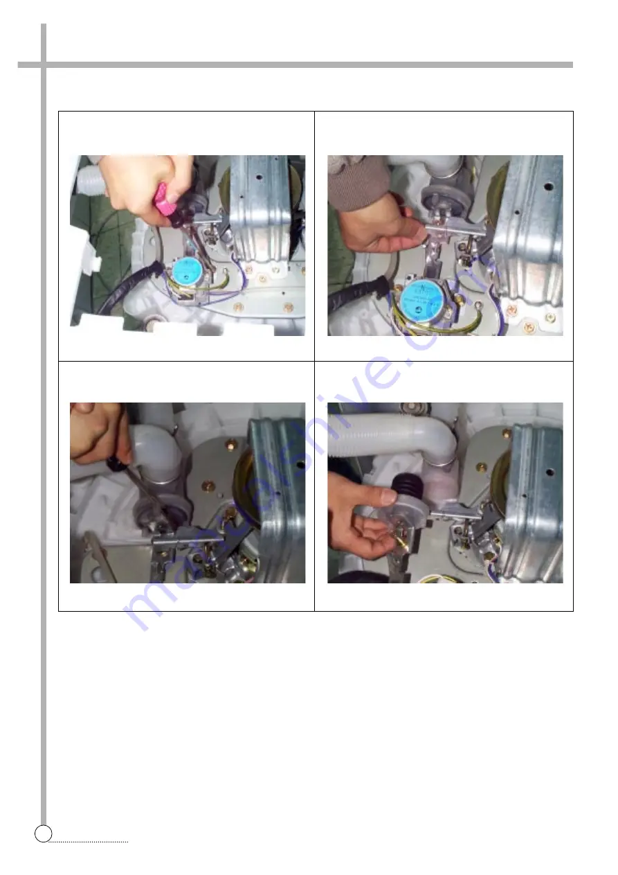
DIRECTIONS
1
Lay the front of the washer on the floor.
2
Loosen two special screw of motor synchronous.
5
Turn the valve by using screw driver as shown in picture.
3
Take out the wire of motor synchronous from the braket.
4
Separate the motor synchronous from the base.
6
Remove the valve lid from the valve drain assy.
MOTOR SYNCHRONOUS AND VALVE REPLACEMENT (NON PUMP MODEL)
Summary of Contents for DWF-200M
Page 31: ...30 WIRING DIAGRAM APPENDIX Wiring Diagram non Pump Single Valve ...
Page 32: ...31 WIRING DIAGRAM Non Pump Multi Valve ...
Page 33: ...32 WIRING DIAGRAM Pump Single Valve ...
Page 34: ...33 WIRING DIAGRAM Multi Valve ...
Page 35: ...34 PARTS DIAGRAM Inverter Single Valve ...
Page 36: ...35 PARTS DIAGRAM Parts Diagram ...
Page 37: ...36 PARTS DIAGRAM ...
Page 38: ...37 PARTS DIAGRAM ...
Page 39: ...38 PARTS DIAGRAM ...
Page 44: ...43 CIRCUIT DIAGRAM Circuit Diagram 201M ...
Page 45: ...44 CIRCUIT DIAGRAM Circuit Diagram 200M 240M ...
Page 46: ...45 CIRCUIT DIAGRAM Circuit Diagram 200MV 240MV ...


