


3
SAFETY&PRECAUTIONS
4. Leakage current test
Confirm specified or lower leakage current between B(earth
ground, power cord plug prongs) and externally exposed accessi-
ble parts (RF terminals, antenna terminals, video and audio input
output terminals, microphone jacks, earphone jacks, etc.)
Measuring method:(Power ON) Insert load Z between B(earth
ground, power cord plug prongs) and exposed accessible parts.
Use on AC voltmeter to measure across both terminals of load Z.
See figure2 and following table.
Leakage current ratings for selected are as
AC Line Voltage
Region
Load Z
Leakage Current(
i
)
Clearance Distance(d),(d’)
100V
Japan
1
K
Ω
i
<1mArms
Exposed accessible parts
110 to 130V
USA &Canada
15k
m
F
1
K
Ω
i
<0.5mArms
Exposed accessible parts
110 to 130V
200 to 240V
Europe
Australia
2
K
Ω
i
<0.7mApeak
i
<2mAdc
Antenna earth terminals
50
K
Ω
i
<0.7mA peak
i
<1mAdc
Other terminals
This table is unofficial and for reference only. Be sure to confirm the precise values
for your particular country and locality.
NOTE
Summary of Contents for DV-K813S Series
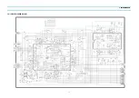
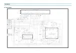
Page 15: ...14 CIRCUIT DIAGRAM 1 POWER CIRCUIT DIAGRAM 230V ONLY...
Page 16: ...15 CIRCUIT DIAGRAM 2 SYSCON CIRCUIT DIAGRAM...
Page 17: ...16 CIRCUIT DIAGRAM 3 A V CIRCUIT DIAGRAM SECAM...
Page 18: ...17 4 PIF CIRCUIT DIAGRAM CIRCUIT DIAGRAM...
Page 19: ...18 CIRCUIT DIAGRAM 5 HIFI SW CIRCUIT DIAGRAM...
Page 20: ...19 CIRCUIT DIAGRAM 6 SW CIRCUIT DIAGRAM...
Page 25: ...24 COMPONENTS LOCATION GUIDE ON PCB BOTTOM VIEW 1 PCB MAIN...
Page 26: ...25 DISASSEMBLY 1 PACKING ASS Y...
Page 27: ...26 DISASSEMBLY 2 FRONT PANEL ASSEMBLY DV K813S SERIES DV K823S SERIES...
Page 28: ...27 DISASSEMBLY DV K873S SERIES DV K893S SERIES...
Page 29: ...28 DISASSEMBLY DV K843S SERIES DV K863S SERIES...
Page 30: ...29 DISASSEMBLY DV K9A3S SERIES...


