-10-
ALIGNMENT INSTRUCTION
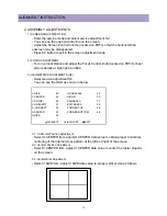
2. ASSEMBLY ADJUSTMENTS
1) SCREEN ADJUSTMENT (S2)
- Enter the service mode and select service adjustment S2.
- You can see the one horizontal line on the screen.
- Adjust the Screen Control Volume (located on FBT) so that the horizontal line
onscreen may be disappeared.
- Press S2 button to exit in the screen adjustment mode.
2) FOCUS ADJUSTMENT
- Turn in a local station and adjust the Focus Control knob (located on FBT) for best
picture details at high light condition.
3) GEOMETRIC ADJUSTMENTS (S6)
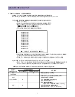
- Select service adjustment S6
- You can see the OSD as shown in below.
V.SIZE
43
H.PARALLEL
33
V.CENTER
42
H-BOW
35
V.SLOPE
28
PARABOLA
17
V.LINEARITY
37
EW TRAPEZ
38
S_CORRECT
32
CORNER TOP
54
H.CENTER
45
CORNER BOTTOM
46
H.SIZE
54
3-1. Horizontal Position Adjustment
- Select H.CENTER item, adjust H.CENTER data value to obtain proper horizontal
centering of the internal cross pattern at the left and right of the screen.
3-2. Vertical Position Adjustment
- Select V.CENTER item, adjust V.CENTER data value to center the raster properly
on the screen.
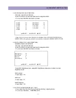
3-3. Vertical Size Adjustment
- Select V.SIZE item, adjust V.SIZE data value to proper vertical size as follows.
VW
SELECT
C B
ADJUST
L
EXIT
Summary of Contents for DTQ-29U1SCV
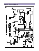
Page 7: ...6 CIRCUIT BLOCK DIAGRAM...
Page 27: ...26...
Page 28: ...27...
Page 31: ...30...
Page 32: ...31...
Page 33: ...32...


