-11-
ALIGNMENT INSTRUCTION
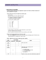
3-3. Vertical Size Adjustment
•
Select “V.SIZE” item, adjust “V.SIZE” data value to proper vertical size as follows.
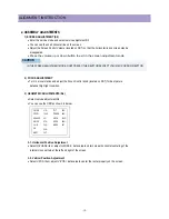
4) WHITE BALANCE ADJUSTMENT(S8)
•
Receive a good local channel.
•
Enter the service mode and select service adjustment S8.
•
You can see the OSD as shown in below.
•
Using volume up or volume down, adjust service adjustment data of RD/GD/BD and RB/GB/BB until a good gray
scale with normal whites is obtained.ALIGNMENT INSTRUCTIONS
•
Press the DISPLAY button to memorize the data.
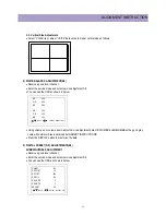
5) DIGITAL PRESET(D.P) ADJUSTMENTS(S9)
SUBBRIGHTNESS ADJUSTMENT
•
Receive a good local channel.
•
Enter the service mode and select service adjustment S9.
•
You can see the OSD as shown in below.
RD
800
GD
800
BD
800
RB
350
GB
350
BB
350
MOVE ADJUST RECALL : SET
DP-BRI
160
DP-CONT 13
DP-TINT
200
DP-COL
100
DP-OVPK 0
DP-UNPK 2
BRI-SET 80
MOVE ADJUST RECALL : SET
Summary of Contents for DTQ 27U4SC
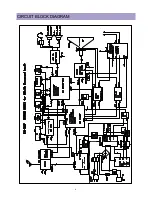
Page 7: ... 6 CIRCUIT BLOCK DIAGRAM ...
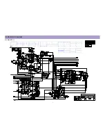
Page 14: ... 13 SCHEMATIC DIAGRAM 20U4 SHEET 1 ...
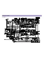
Page 15: ... 14 SCHEMATIC DIAGRAM 20U4 SHEET 2 ...
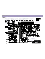
Page 16: ... 15 SCHEMATIC DIAGRAM 27U4 SHEET 1 ...
Page 17: ... 16 SCHEMATIC DIAGRAM 27U4 SHEET 2 ...
Page 46: ... 45 PRINTED CIRCUIT BOARD CN 230F MAIN ...
Page 47: ... 46 PRINTED CIRCUIT BOARD CN 230F 20U4 CRT ...
Page 48: ... 47 PRINTED CIRCUIT BOARD CN 230F 27U4 CRT ...
Page 57: ... 56 WAVEFORMS Appendix 17 SVM Q909 BASE 18 I901 PIN7 ROUT ...
Page 64: ...PRINTED DATE Mar 2003 ...


