6
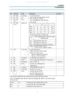
Pin
Terminal
Name
Explanation
Remarks
16
P87 / AN7
SPARE A/D
-16 pin is a spare pin.
-13 pin to 16 pin.
-4 bit input/output port, Nch-OD output.
-Input or output can be specified for each bit.
-Other function.
.AD converter input port (4 lines)
17
/RES
/RES
-Reset terminal.
-Active Low.
18
FILT
Filter
-Filter terminal for PLL.
-Output terminal.
19
CVTN
CVSB IN
-Video signal input terminal.
20
/VS
/VS
-Vertical synchronization signal input terminal.
21
/HS
/HS
-Horizontal synchronization signal input terminal.
22
R
R
-Red output terminal of RGB image.
23
G
G
-Green output terminal of RGB image.
24
B
B
-Blue output terminal of RGB image.
25
BL
BL
-Fast blanking control signal.
-Switch TV image signal and caption / OSD image
signal.
-Output terminal.
26
I
I
-Intensity output terminal of RGB image signal.
-Output terminal.
27
P60/ SDA 0
ROM Data
Main IC Data
-6-bit input/ output port.
-Input/ output can be specified for each bit.
-Other function.
28
P61 / SCLK 0
ROM CLK
Main IC CLK
29
SDA 1
Tuner Data
30
P63 / SCLK 1
Tuner CLK
IC DESCRIPTION
APPENDIX
P60
IIC0 data I/O.
P61
IIC0 clock output.
P62
IIC1 data I/O.
P63
IIC1 clock output.
All manuals and user guides at all-guides.com

