13
IC description
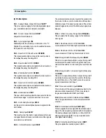
1.1.9 PWM Output
Control of TV settings is able to be made with up to eight
8-bit PWM outputs, with a frequency maximum of
23,437Hz at 8-bit resolution(INTCLK=12 MHz). Low reso-
lutions with higher frequency operation can be pro-
grammed.
1.1.10 Serial Peripheral Interface (SPI)
The SPI bus is used to communicate with external
devices via the SPI, or bus communication stan-
dards. The SPI uses one or two lines for serial data and a
synchronous clock signal.
1.1.11 Standard Timer (STIM)
The Standard Timer includes a programmable 16-bit
down counter and an associated 8-bit prescaler with Sin-
gle and Continuous counting modes.
1.1.12 Analog/Digital Converter (ADC)
In addition there is a 3 channel Analog to Digital Con-
verter with integral sample and hold, fast 5.7us conver-
sion timer and 6-bit guaranteed resolution.
I C
2
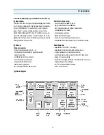
Register File based 8/16 bit Core Architecture with
RUN, WFI, SLOW and HALT modes
to operating temperature range
Up to 24 MHz Operation @5V 10%
Minimum instruction cycle time : 375ns at 16MHz inter-
nal clock
64K Bytes ROM
256 Bytes RAM of Register file(accumulator or index
registers)
256 Bytes of on-chip static RAM
8K Bytes of TDSRAM(Teletext and Display RAM)
56-lead Shrink DIP package
28 fully programmable I/O pins
Serial Peripheral Interface
Flexible Clock controller for OSD, Data Slicer and Core
clocks running from one single low frequency external
crystal.
Enhanced Display Controller with 26 rows of 40/80
characters
- Serial and Parallel attributes
- 10x10 dot Matrix, 512 ROM characters, definable by
user
- 4/3 and 16/9 supported
(2) Feature
0 C
O
70 C
O
+
_
- Rounding, fringe, double width, double height,
scrolling, cursor, full background colour,
semitransparent mode and reduced intensity colour
supported
Teletext unit, including Data slicer, Acquisition Unit and
up to 8K Bytes RAM for Data Storage
VPS and Wode Screen Signalling slicer
Integrated Sync Extractor and Sync Controller
14-bit Voltage Synthesis for tuning reference voltage
Up to 6 external interrupts plus 1 non-maskable inter-
rupt
8x8-bit programmable PWM outputs with 5V open-
drain or push-pull capability
16-bit Watchdog timer with 8-bit prescale
16-bit standard timer with 8-bit prescaler usable as a
Watchdog timer
3-channel Analog-to-Digital converter ; 6-bit guaran-
teed
Rich instruction set and 14-Addressing modes
Versatile Development Tools, including Assembler,
Linker, C-compiler, Archiver, Source Level Debugger
and Hardware Emulators with Real-Time Operating
System available from third parties
Piggyback board available for prototyping
Summary of Contents for DTJ-28G8F
Page 6: ...5 3 Circuit Block Diagram...
Page 7: ...6 4 Alignment Instructions 4 1 User Remocon R 22D05...
Page 8: ...7 R 23D05 Alignment Instructions...
Page 15: ...14 3 Block Diagram IC description...
Page 24: ...23 3 Block Diagram IC description...
Page 50: ...49 Mechanical Exploded View 5 DTJ 28G7F...
Page 52: ...51 10 Printed Circuit Board...
Page 53: ......

