4
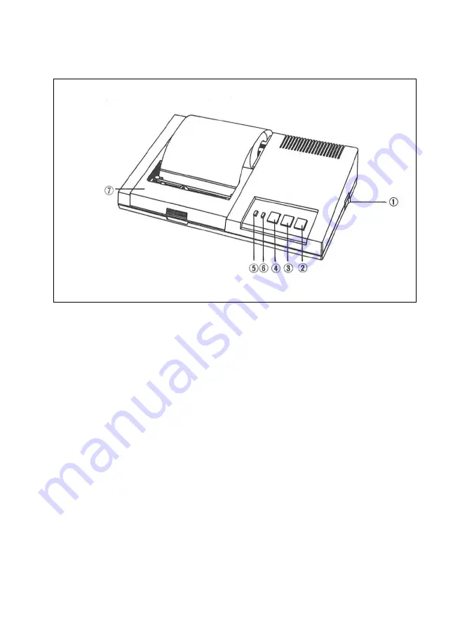
(3) Names of Sections and Operation
DPL-400 Main Part
1. Power switch: Turning on this switch, then the Power direction Lamp will be
on.
2. Pen change switch: If you press this switch when you insert or remove the
pen, pen Holder moves to the right. Then pen change can be possible.
3. Color select switch: On pressing this switch, pen holder rotates to change the
color. And on pressing the line feed switch at the same time, this will be
operated as a function like ‘‘A’’ command word. And turning on the power
pressing this switch, this switch examines the Ink condition of pen by drawing
4 rectangulars on paper in each color.
4. Line feed switch: Pressing this switch make pen Holder move to the left-
outside of the print range and papers will be sent out. And turning on the
power pressing this switch executes self test.
5. Power indicator: Directs the on-power situation
6. Busy Indicator: Directs the receiving-the-data situation from msx Host
computer
7. Top cover: When changing the pen and the paper, change them opening this
cover. Close this cover when printing.
Summary of Contents for DPL-400
Page 2: ......
Page 3: ......
Page 8: ...5 MECANISM UNIT PEN HOLDER UNIT...
Page 14: ...11 3 DPL 400 Code Table DPL 400 as follows has a code Table perfectly identified with MSX Code...
Page 35: ......
Page 36: ......
Page 37: ......


