breaking down.
E) Charge the accumulator under the place with better ventilation. Before charging, open the
accumulator cover. If electrolytic temperature is over 45
°C
should break down charging.
REMARK: When the accumulator is connected with generator DC terminals, do not try to start
the engine in car or in vessel.
2. MAINTENANCE
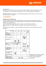
Maintenance at fixed period
For the generator works in order, maintenance at fixed period is very important. The diesel
generator is consisted of diesel engine, alternator, control panel, frame etc. Please read relative
manual for the maintenance.
Before maintaining the generator, stop the engine. The surrounding condition
of the generator is of better ventilation, because engine exhaust includes harmful
CO.
After stopping the generator, clean it immediately to prevent the corrosion and to remove the
sediment.
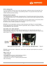
When starting the generator each time, should check oil level. If not being enough, should add
the lube oil to the stipulated level. Draining off lube oil can be immediately done after engine
stopped, because it is difficult to drain off the oil thoroughly when the engine is in cold state,
shown in Fig. 2-4.
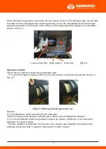
Check air cleaner
Check the air cleaner of silent diesel generator sets
(
1
)
Loosen the clipper to take out the cover of air cleaner for getting the element, shown in
Fig. 2-5
Remark
:
1)
It is forbidden to clean the element with detergent.
2)
When output power drops or exhaust gas is black, should change the element.
3)
It is not permitted to start the generator without air cleaner. Otherwise, it will cause the
generator to be worn easily.
(
3
)
After installing the element, fit the cover of air cleaner and retighten the clipper firmly.
pressure drops less than or equal to those given in table 1 below:
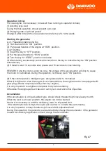
Check the air cleaner of open frame diesel generator sets
(
1
)
Unscrew the bolt and take out side plate, shown in Fig. 2-6
Remark
:
1)
It is forbidden to clean the element with detergent.
2)
When output power drops or exhaust gas is black, should change the element.
3)
It is not permitted to start the generator without air cleaner. Otherwise, it will cause the gene-
rator to be worn easily.
(
2
)
After installing the element, fit the cover of air cleaner and retighten the clipper firmly.
Checking the alternator
Turn off main switch for unloading, like lamp and motor etc.
Before starting the generator, must turn off main switch. If not in this position, it is very dange-
rous for the generator to be started with the load.
The alternator should be grounded correctly to prevent the shock by electricity.
The fuel and lube oil have been removed prior to delivery.
When filling in the fuel, should
check whether there is the air in the piping before starting. If existing, should drain off the air by
unscrewing on fuel pump till no air bubbling comes out from the diesel, then retighten the
screw again
Checking & operating the engine
Checking lube oil level
Check lube oil level prior to each starting. If the engine works under lack of lube oil, oil tempera-
ture will rise quickly and the engine will be clipped. If the engine works under enough lube oil, it
is very easy to make lube oil burn, resulting in speed increasingly to damage the engine. Hence,
it is very important to ensure that oil level is between upper limit and lower limit in oil dipstick.
(
Screw the dipstick, the oil level should be between the upper and lower level limit
,
shown in
Fig2—2.3.2
)
Operation in trial
For new engine, it is necessary to have 20 hour running-in operation initially.
(1) Avoiding over-load
During the trial operation, should prevent over-load.
(2) Changing lube oil at fixed period
Change it after initial 20 hours operation and refer to2-2.3.1 afterwards.
Starting the generator
2-4.1 Preparation before starting
(1) Turn fuel switch to “ON” position.
(2) Put speed handler of the engine at “RUN” position.
2-4.2 Starting
(1) Insert the key to “OFF”position.
(2) Put the speed handler to “RUN” position
(3) Turn the key to “START” position clockwise.
(4) After starting successfully, remove the hand from the key to make the key be “ON”position
automatically.
(5) If failed to start 10 seconds later, please wait 15 seconds for next starting.
REMARK: If starting motor works too long, the voltage of the accumulator will drop to cause
the motor to be blocked. During the operation, let the key be in “ON”position.
(6) If the control panel is intelligent type, also please refer to its manual
When it is difficult to start the engine in cold temperature, the engine need to be equipped with
glow plug. (Please require specially when buy engine).
It is very important to retighten oil dipstick firmly before starting.
Otherwise the engine parts will be worn out by rain, dust and other impurities.
Accumulator
If the accumulator is of liquid-added type, should check the electrolytic level every month.
When the level is at lower position, the engine can not be started.
Hence it is necessary to add the distillatory water to stipulated limit.
If the electrolytic level is high, the liquid will overflow to corrode the parts nearby.
It is very important to keep the electrolytic level within stipulated level
During the operation, the generator can automatically charge the accumulator. If the generator
is used for stand-by application, should charge the accumulator.
If the accumulator is of valve-controlled lead-acid type, it will be charged if necessary.
Do not let two terminals contact with each other, which will make the circuit short.
Operating the generator
- Operating the engine.
A) Start the engine
B) Preheat the engine for three minutes without load.
C) Do not alter fuel quantity controller or speed limiter (having adjusted before delivery).
Otherwise, the performance of the engine will be affected,
- Make the inspection during the operation.
A) Check whether there is abnormal sound or strong vibration.
B) Check whether the engine works out of order.
C) Check the color of exhaust gas: black or too white.
If any of them mentioned above happens, should stop the generator and then contact with
local dealer or our company directly.
Adding the load
- Load
Add the load according to stipulated data.
- AC application
A) When starting the generator, should keep the indicating light on to observe work condition.
B) The generator should be run at rated speed (Put the speed handler to “RUN” position.).
Otherwise, the voltage, frequency and power will be lower than rated limit, shown in 1-1Main
technical specification and data.
C) When voltage indicating on control panel reaches ±10% of rated limit, can add the load.
D) Following table shows load usage.
REMARK: Do not start more than two machines in the same time. Only start them one by one.
Do not use floodlights with other machines meanwhile.
DC application
DC terminal output is 12V 8.3A. Red terminal refer to the positive poles of battery. It is can also
for load with rated voltage at 12V and charge 12V battery.
A) When adopting automatic-type accumulator, must disconnect the wire from the cathode of
the accumulator when charging.
B) Starting diesel generator.
C) Connect charging wire between accumulator terminal and generator anode. Pay attention to
the anode and cathode. Otherwise, it will make the generator and accumulator be damaged.
When charging big capacity accumulator, the charging current should be less than 8A.
Otherwise, the fuse will burn.
D) During charging the accumulator will make inflammable gas. So do not let the spark, flame
and cigarette be around it. For avoiding the spark near the accumulator, connect charging wire
with the accumulator at first before charging and first disconnect from the generator after
- Change lube oil
(
20 hours for first time and 100 hours for next three times and 200 hours for
normal operation.
)
Loosen oil-drained plug located at the bottom of cylinder block when the engine is at hot state.
After removing used lube oil, screw in the plug and add the stipulated oil.
- Change the element of air cleaner
Do not clean the element with the detergent.
Change fuel filter
Often clean fuel filter to ensure that the engine can deliver maximum power
A) Close fuel switch
B) Change the element with loosening the covers of oil/water separator.
。
- Re-checking bolt retightened moment of cylinder head with special tool, shown in engine
manual.
- Check the injector and fuel pump
- Adjust the clearance of intake / exhaust valves
- Grind the intake / exhaust valves
- Change piston rings
Need special tool and the protection should be paid attention to.
- Check the electrolytic and charge the accumulator
The 12V accumulation, used in the engine, will consume the electrolytic due to charging and
discharging continuously.Check the accumulator before starting. The distillatory water can be
added to stipulated limit if necessary. If the accumulator is damaged, exchange it in time.
Long-term storage
When the generator is not operated for more than three months, it should be stored. After the
storage for six months, be restored again as follows.
A) Drain off the fuel and lube oil.
B) Remove the dust and the oily.
C) Clean the crankcase and gear chamber with diesel and kerosene. Then drain off them.
D) Inject rust-proofed oil or lube oil without water (heat the lube oil to about 120
°C
till no foam
exists. into crankcase at stipulated level. Then run the engine for three minutes to splash the oil
to the surface of all moving parts. Last drain off the oil after engine stopped.
E) Inject rust-proofed oil or lube oil without water into intake manifold and then rotate the
engine rapidly. Last make intake/exhaust valve be at close state.
F) Dismantle cylinder head cover and brush rock arm etc. with a few rust-proofed oil or lube oil
without water.
G) Wrap air cleaner and muffler with wet-proofed paper to prevent the dust and moisture going
in.
H) Remove the dust and the oily on the frame and control panel.
I) Take out the key
J) The generator should be stored at a place with better ventilation, clean, dry and no corrosive
material nearby.
3. TROUBLE SHOOTING AND REMEDY
If the generate can not deliver the output after checking, please contact with RUNSUN com-
pany or local dealer.
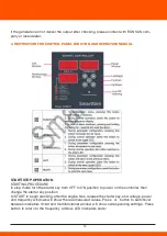
4. INSTRUCTION FOR CONTROL PANEL FUNCTION AND OPERATION MANUAL
START/STOP OPERATION
STARTING PROCEDURE
In stop mode turn the starter key from OFF to ON position to power on the controller, then
change the starter key position
to START to begin cranking; after the engine fires, release the starter key, and voltage, power
and frequency windows will show the real measured values. Press or button to switchover
between indicators 1#-6# and multifunctional window will show corresponding settings. Press
button to return to the frequency window. LED indicators state:
1# Frequency (Hz)
2# Current (A)
3# Battery voltage (V)
4# Run time (H)
5# Engine temp.(
°C)
6# Generator temp.(
°C
)
7# Auto protection If on, auto protection is enabled; if not,it is disabled.
8# Run on indicator Fuel relay output indicator
9# Crank indicator Start output indicator
10# Engine oil warning Low oil pressure indicator
NOTE: Before starting the engine please make sure that all the parameter settings are correct.
NOTE“Engine oil warning”indicator operates according to the oil pressure switch. Before the
start of the gen-set, the light must be on; if it is not, it means that oil pressure switch or its
return circuit is faulty; in this case please do not proceedbefore clearing up the problem.
STOPPING PROCEDURE
1) Auto stop
If auto protection condition occurs, the system will be stopped automatically;
During normal running of the gen-set, if low oil pressure signal is detected,
the set will be stopped.
2) Manual stop
Under any circumstances, if starter key is turned from ON to OFF position,it will lead to shut-
down.
AUTO PROTECTION
In auto protection mode, except for low oil pressure protection, all the other protections (volta-
ge, frequency, overload, temperature) are active.
1) Voltage protection
When the limits of rated voltage are exceeded by ±10%, Voltage LED starts flashing; after 7
seconds delay in case of under voltage or 3 seconds delay in case of over voltage, alarm
shutdown is initiated. After that voltage LED continues to flash and shows pre-alarm value.
2) Frequency protection
50Hz
:
(45~55)Hz
60Hz
:
(55~65)Hz
When the set value is exceeded, frequency LED starts flashing; after 7 seconds delay in case
of under frequency and 3 seconds delay in case of over frequency, alarm shutdown is initiated.
After that frequency LED continues to flash and shows pre-alarm value.
3) Overload protection
If the set value is exceeded by 5% or less, alarm will not be initiated;
If the set value is exceeded by more than 5%, power LED will start flashing;
If the set value is exceeded by 5-7.5% and continuous for more than 3 hours, then alarm shut-
down will be initiated;
If the set value is exceeded by 7.5-10% and continues for more than 1 hours, alarm shutdown
will be initiated;
and shows pre-alarm value.
4) Low oil pressure protection
Irrespective of whether auto protection mode is enabled or not, low oil pressure will lead to
automatic disconnection of oil circuit;
5) High engine temperature protection
If engine temperature exceeds 108 , LED window starts flashing; after 7 second delay, protec-
tion begins; LED window continues to flash and shows pre-protection value (for air-cooled
engine);
6) High generator temperature protection
When generator temperature exceeds 95 , LED window starts flashing; after 7 second delay,
protection begins; LED window continues to flash and shows pre-protection value;
7) Battery voltage protection
Battery voltage protection is enabled irrespective of whether auto protection mode is enabled
or not and whether gen-set is running. If battery voltage value is lower than 8V or higher than
16.5V, LED display or indicator starts flashing, butshutdown protection is not initiated.
NOTE: During Safety On delay, protection is disabled; after Safety On Delay,
when voltage, frequency, overload, high temperature protection is initiated, fuel output deacti-
vates.
interva
l
item
ever
yda
y
20 h
100 h
200
h
500 h
every
year or
1000 h
Check the fuel
○
Clean fuel tank
○
Check oil leakage
○
Check each fastening
●
(
retighten
cylinder head
bolt
)
Change lube oil
○
(
first
time
)
○
(
next
three
times
)
○
Clean the element of air
cleaner
(
shorten the interval in more
dust condition
)
○
○
(
change
)
Clean fuel filter
○
○
(
change
)
○
(
chang
e
)
Check fuel pump
●
Check the injector
●
Check f
uel pipe
●
(
change if
necessary
)
Adjust intake/exhaust
valve clearance
●
(
first
time
)
Grind intake/exhaust
valve
●
Change piston ring
●
Check the electrolytic or
voltage of accumulator
(
every month
)
REMARK: The mark “
” indicates
special spanner to be used.
Please contact RUNSUN
local dealer.
9


