


16
15
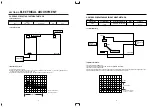
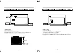
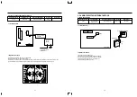
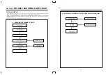
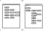
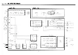
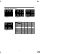
3. AFT COIL
• Connection Method
• Adjustment Procedure
1) Connect the TEST circuit to PIN
2
of H101
2) 12V to pin
6
and GND to PIN
7
of H101
3) Connect the signal Generator output to PIN
8
, and GND to PIN
7
4) Connect the oscilloscope to check point
5) Adjust L110 to obtain 2.3V ± 0.15V DC at “A” point DC Voltage change rapidly.
S/N : 97P650031A
C111
L110
IC101
R191
L103
C105
Z103
C122
Q102
C112
H101
1
8
L101
Q101
1
11
10
1
5
CH-1
OSCILLOSCOPE
CH-2
±12V
POWER SUPLLY
GND
2.3V±0.15V
OUT
SIGNAL GEN
GND
VCC+12V
43K
33K
18K
"A"
0.01µF
0.47µF
/50V
TEST CIRCUIT
#8
#7
"A"POINT
#8
#7
#6
#2
#6
#7
#2
l102
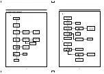
Carrier : Refer to input
signal table
on page 13.
+
Adj. Location
Checking Point
Measuring Equipment
Input signal
Signal gen
Refer to
L110
“A” Point
Oscilloscope
the
Power supply
table on page13.
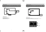
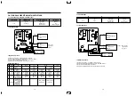
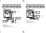
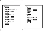
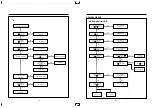
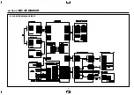
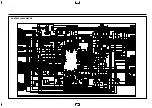
4. RF AGC
• Connection Method
• Adjustment Procedure
1) 12V to PIN
6
, and GND to PIN
7
of H101
2) Connect the signal generator output to pin
8
and GND to PIN
7
3) Connect the oscilloscope to check point
4) Adjust R191 to obtain 6.0 ± 0.2V DC at check point.
S/N : 97P650031A
C111
L110
IC101
R191
L103
C105
Z103
C122
Q102
C112
H101
1
8
L101
Q101
1
11
10
1
5
CH-1
OSCILLOSCOPE
CH-2
OUT
SIGNAL GEN
GND
GND
+12V
POWER
SUPPLY
#6
#7
#6
#7
#8
#1
Z102
L108
L107
20
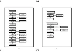
Carrier : Refer to input
signal table
on page 13.
Adj. Location
Checking Point
Measuring Equipment
Input signal
H101
Signal gen
Refer to
R191
PIN
1
Oscilloscope
the
Power supply
table on page13.
Summary of Contents for DV-F202 Series
Page 19: ......
Page 20: ...SECTION 5 CIRCUIT DIAGRAM 5 1 CONNECTION DIAGRAM CIRCUIT 33...
Page 21: ...5 2 POWER CIRCUIT 230V ONLY 34...
Page 22: ...5 3 POWER CIRCUIT WIDE RANGE 35 M M M M...
Page 24: ...5 4 SERVO LOGIC CIRCUIT 37 M M...
Page 25: ...5 5 LOGIC CIRCUIT WITH SHUTTLE STATION F542 F342 SERIES 38 1 3 2 1 2 3...
Page 26: ...5 6 LOGIC CIRCUIT F442 F242 F462 F262 F402 1 F202 1 SERIES 39 1 2 3 3 2 1...
Page 27: ...5 7 LOGIC CIRCUIT F562 F362 SERIES 40...
Page 28: ...5 8 LOGIC CIRCUIT F402 2 F202 2 SERIES 41 1 2 3 3 2 1...
Page 29: ......
Page 30: ......
Page 31: ...5 11 PIF CIRCUIT 44 M M M...
Page 32: ......
Page 34: ...5 13 VIDEO CIRCUIT 47...
Page 35: ......
Page 36: ...5 14 OSP CIRCUIT 48 5 15 COLOR CONVERTER 49...
Page 37: ...5 17 IF MODULE CIRCUIT 51 5 16 LINEAR AUDIO CIRCUIT 50 M M M M M M M...
Page 38: ......
Page 39: ...5 19 VPS PDC CIRCUIT AUTO SET 53 5 18 VPS CIRCUIT 52...
Page 40: ...5 21 REMOCON CIRCUIT VR F2BC 55 5 20 REMOCON CIRCUIT VR F3BC 54...
Page 41: ...5 22 REMOCON CIRCUIT VR F2BT 56...
Page 50: ......
Page 51: ......
Page 52: ......


