DAEWOO ELECTRONICS DLM-32C5 Instruction Manual Download Page 10

Antenna

Connection

9

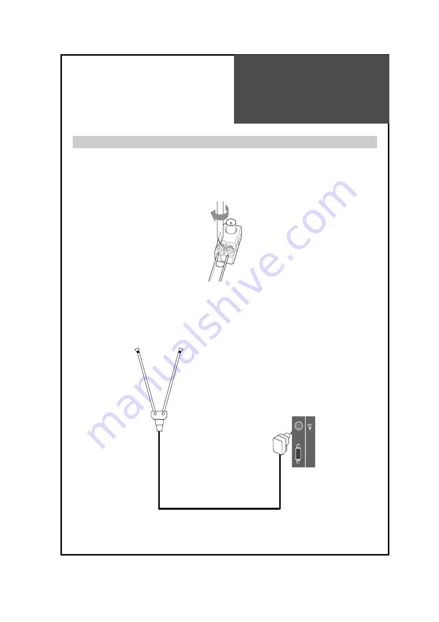
Indoor Antenna Connection

1. Connect the feeder cable of the antenna to the combining adapter.

WHEN THE IMAGE IS NOT CLEAR : 

Unclear screen image and bad reception may be a cause of wrong
antenna connection. Be sure to check its direction and place when
installing.

2. Connect the combining adapter to the antenna input at the left side of the TV set.

WHEN USING THE COMBINING ADAPTER : 

You may obtain the combining adapter at your closest
Service Center.

UP-GRADE

PORT

Antenna Input

BACK OF THE TV SET    

All manuals and user guides at all-guides.com

Summary of Contents for DLM-32C5

Page 1: ...48586601E101 R0 All manuals and user guides at all guides com a l l g u i d e s c o m...

Page 2: ...LCD TELEVISION INSTRUCTION MANUAL DLM 32C5 LPB SPB DLM 32C7 LPBD SPBD DLM 32U1 LPB SPB DLM 32U2 LPB SPB DLM 37U7LPBD DLM 42C5LPB DLM 42C7LPBD All manuals and user guides at all guides com...

Page 3: ...SIDE REFER SERVICING TO QUALIFIED SERVICE PERSONNEL The lightning flash with arrowhead symbol within an equilateral triangle is intended to alert the user to the presence of uninsulat ed dangerous vol...

Page 4: ...cabinet unless proper ventilation is provided Leave a minimum 10 cm gap all around the unit 8 Power Source This TV should be operated only from the type of power source indicated on the marking label...

Page 5: ...l 18 Damage Requiring Service Unplug the TV from the wall outlet and refer servicing to qualified service personnel under the following conditions a When the power supply cord or plug is damaged b If...

Page 6: ...air Do not put on or use the product near water and moisture such as in a bathroom washbowl etc It may be a cause of fire and electric shock hazards To prevent fire and damages to the product unplug t...

Page 7: ...f hazardouselectricshockandfireiftheantenna touchesorfallsontheelectricwire thus itmustbe installedfirmly andfaraway from thecables This section must be read carefully and followed by the user prior t...

Page 8: ...olby Digital AMP 19 Name of Each Part 20 Basic Guide Parts of the Remote Controller 22 Method To Use Basic Menu 24 To Watch TV 25 Setting Up TV Stations 27 Selection of AV and Multimedia Input Signal...

Page 9: ...es Cover Bottom When you install wall mounting you set up cover bottom like upper picture Cable holder Microfiber sheet 32U1 U2 ONLY 1 2 3 The method of wire arrangement 1 Assemble the cable holder en...

Page 10: ...n may be a cause of wrong antenna connection Be sure to check its direction and place when installing 2 Connect the combining adapter to the antenna input at the left side of the TV set WHEN USING THE...

Page 11: ...f co op apartments When a coaxial cable is used Plug the coaxial cable to the antenna socket and fix it firmly by turning it to the right When a feeder cable is used Plug the coaxial cable to the ante...

Page 12: ...Antenna connection such as VHF or and UHF may be necessary for installation at private houses Single Antenna Connection Separate Antenna Connection UP GRADE PORT VHF Antenna UHF Antenna ANT CABLE TV...

Page 13: ...2 st TV set 4 Turn on the TV sets Note If S video and RCA jack are connected the same time The TV set will only detect the S Video mode If your AV device has both Video OUT terminal and S Video OUT te...

Page 14: ...for better picture quality Watching the Camcorder Recording on TV 1 Prepare the S video and RCA connector 2 These connectors connect to S Video or AV1 AV2 as shown in the picture below 3 Turn on the T...

Page 15: ...eck the colour of the cable between the DVD and TV set Note If S video and RCA jack are connected at the same time the TV set will only detect the S Video mode If your AV device has both Video OUT ter...

Page 16: ...DIO L PC AUDIO DIGITAL AUDIO Set Top Box Set Top Box INPUT HDMI 1 HDMI 2 AV1 MONITOR OUT COMPONENT INPUT PC INPUT OPTICAL Pr Pb Y VIDEO R AUDIO L R AUDIO L PC AUDIO DIGITAL AUDIO When connecting with...

Page 17: ...MI 2 AV1 MONITOR OUT COMPONENT INPUT PC INPUT OPTICAL Pr Pb Y VIDEO R AUDIO L R AUDIO L PC AUDIO DIGITAL AUDIO 1 First adjust resolution of the PC Refer to table in page 17 2 Connect between PC and TV...

Page 18: ...ur contact the graphic card company for help Multi input resolution available in LCD TV Resolution V freq HDMI PC D Sub Component Standard 60Hz O O X 640 X 480 72Hz O O X 75Hz O O X VESA Standard 60Hz...

Page 19: ...V1 MONITOR OUT COMPONENT INPUT PC INPUT OPTICAL Pr Pb Y VIDEO R AUDIO L R AUDIO L PC AUDIO DIGITAL AUDIO External Input Connection Source Antenna Input Connection Watching cable television is only pos...

Page 20: ...INPUT OPTICAL Pr Pb Y VIDEO R AUDIO L R AUDIO L PC AUDIO DIGITAL AUDIO Surround L Surround R R L Center Woofer Dolby Digital AMP I N P U T Optical output If you connect the optical output to a Dolby...

Page 21: ...is button to change from TV STANDBY mode to TV ON mode Button Use this button to change from TV STAND by mode to TV ON mode LED Indicator Light up red in Stand by mode and Lights up green in TV on mod...

Page 22: ...t 21 INPUT HDMI 1 HDMI 2 AV1 MONITOR OUT COMPONENT INPUT PC INPUT OPTICAL Pr Pb Y VIDEO R AUDIO L R AUDIO L PC AUDIO DIGITAL AUDIO AV 2 S VIDEO VIDEO R AUDIO L Rear Panel All manuals and user guides a...

Page 23: ...current state is ST BY you can turn on the TV using a digit key Then a PROGRAMME is selected according to digit number 7 S EFFECT Press to use a spatial sound effect 8 You can select sound mode in Mon...

Page 24: ...you can swap the main screen for sub screen 26 P INPUT Sub Screen input mode change as follows POP table mode Note This button is also used in teletxt mode 27 When sub screen is RF TV mode in the POP...

Page 25: ...the directions on the screen after selecting the desired item by pressing the button If the setup is completed exit from the menu by pressing the MENU button VOL VOL PR PR SELECT OK Picture Screen So...

Page 26: ...utton of the front side of the set or Remote controller The buttons of the remote control and the main body operate only when AC power is turned on Note You can also turn on the TV using PR or digit k...

Page 27: ...ogram by pressing the PR button or the number button 3 Adjust volume Sound reduces by pressing the VOL button Sound increases by pressing the VOL button Note Sound mutes by pressing the MUTE button 4...

Page 28: ...dit Access 1 Press the MENU button to select the Install menu Move the selection bar to the Install menu with buttons 2 Select the Auto Tuning Place the selection bar on Auto Tuning and press the butt...

Page 29: ...tton to select a program number you want 2 Locate the selection bar on the Manual tuning at the Install menu Press the MENU button to select the Install menu Move the selection bar to the Install menu...

Page 30: ...ve the cursor to Name by pressing buttons You can enter a station name with the and buttons Note Only English is supported in this station name Picture Screen Sound Install Function Move Select Exit M...

Page 31: ...ton The program and station name is highlighed in yellow Move the green block to the desired position using the buttons Press the Move Yellow button again then the program is changed 3 Skipping the Pr...

Page 32: ...aring In the case of connecting both composite video signal and S video signal at the AV3 terminal the S video signal has priority If sound signal is mono only connect the white phono plug to the LEFT...

Page 33: ...Standard 800 X 600 72Hz O O X VESA Standard 75Hz O O X 60Hz O O X VESA Standard 1024 X 768 70Hz O O X VESA Standard 75Hz O O X VESA Standard 1360 6 X 768 60Hz O O X 75Hz O O X 720 X 480 60Hz O X O 72...

Page 34: ...ite Allows the user to customize settings as desired When setting up various screen modes 1 Pressing the NORMAL button The screen changes as follows Normal Movie Dynamic Favourite Normal The screen ad...

Page 35: ...een Sound Install Function Move Select Exit MENU Picture Mode Brightness Contrast Colour Sharpness Tint N R Colour Temp Normal 45 42 40 31 0 Off Normal R G Picture Screen Sound Install Function Move A...

Page 36: ...es image by 1 33 times bigger than 16 9 image Auto This mode will display depending on the signal information of a broadcasting station Aspect Zoom 16 9 Aspect Full Screen Aspect 14 9 Aspect Zoom 14 9...

Page 37: ...Screen menu Press the buttons to adjust the horizontal position of displayed image Picture Screen Sound Install Function Move Adjust Exit MENU 31 44 21 Start PC Auto Adjustment H Position V Position...

Page 38: ...PiP off Side by Side This mode will display two screen left Main and right Sub PiP This mode will dilplay two screen Main is full screen and Sub is xed on the right bottom side Note PiP is just consis...

Page 39: ...If Sub is on Analog Switch the Sub screen in the exterior input cycle RF DVB T AV1 AV2 COMP PC RF 7 Pressing the P PR buttons on the remote controller Sub screen is switched RF mode and change PR Up...

Page 40: ...to enjoy the bass effect Note Whenever you adjust the audio equalizer it stores in the Favourite mode Equalizer High quality sound range adjustment method used for audio product 120Hz 500Hz Low sound...

Page 41: ...Red In Mono reception the depth of sound is improved To switch back to stereo press the button again 2 Adjustment of Bilingual sound In bilingual broadcast reception you can switch from Dual 1 to Dual...

Page 42: ...age by pressing button 3 Select your desired language by pressing the button Then it will be setting automatically The language changes as follows English German French Espanol Italian Danish Suomi Sw...

Page 43: ...ect the Wake Up to On Set the Wake up time and Program in the same way as above for the Clock The set will turn on at the selected time 3 Sleep Mode By pressing the SLEEP button on the remote controll...

Page 44: ...mote control If the TV set is in Child Lock mode the LED will cycle through red green If the Child Lock is On then the set can only be switched back on using the remote control Picture Screen Sound In...

Page 45: ...HOLD symbol appears and the contents of the subpage shown are kept on the screen and no longer updated or switched to other subpages Pressing the HOLD button again the current subpage appears CALLING...

Page 46: ...he antenna or its connection is correct and if not correct the noise antenna fault or connection cable fault Check if car traffic or neon sign disturbs the sound effect Stripes on Check the susceptibl...

Page 47: ...d then no picture will be displayed NO SIGNAL Ensure that the signal cable is firmly connected to PC and TV appears on the screen Image is not Adjust the PHASE control clear Image is not Adjust the H...

Page 48: ...9 16 9 16 9 Resolution 1366 x 768 WXGA 1366 x 768 WXGA 1366 x 768 WXGA 1366 x 768 WXGA Pixel Pitch 0 4215 mm 0 51075 mm 0 200 x 0 600 mm 0 227 x 0 681 mm Contrast Ratio 3000 1 3000 1 3000 1 3000 1 Po...

Reviews: