background image

26

MODULAR ARRAY

EN

IT

CONNECTIONS

LINE IN

 - female XLR connector, which accepts a 

XLR  plug  from  almost  any  type  of  equipment 

with a balanced line level outputs. The XLR input 

is wired as follows:

Pin1 = shield or ground

Pin2 = + positive or “hot”

Pin3 = - negative or “cold”

NOTE - whenever possible, use always balanced 

cables.  Unbalanced  lines  may  also  be  used  but 

nay result in noise over long cable runs.

LINEOUT

 - this XLR male connector is connected in 

parallel with the input female connector. This en-

ables a second units to be daisy-chained to the 

first. It’s thus possible to power several speakers 

using  the  same  signal,  forming  more  powerful 

sound reinforcement systems.

MAINS IN

 - PowerCon® NAC3FCA power input con-

nector  (blue). To  switch  the  amplifier  on,  insert 

the PowerCon® connector and turn it in a clock-

wise direction into the ON position. To switch the 

amplifier off, pull back the switch on the connec-

tor and turn the connector in an anti-clockwise 

direction into the POWER OFF position.

NOTE - In the case of product failure or fuse re-

placement, disconnect the unit completely from 

the mains power. The power cable must only be 

connected to a socket adequate to the specifica-

tions indicated on the amplifier unit. The power 

supply  must  be  protected  by  a  suitably  rated 

thermo-magnetic breaker.

MAINS OUT

  -  PowerCon®  NAC3FCB  power  output 

connector  (grey).  This  is  connected  in  parallel 

with the MAINS IN; the maximum load applicable 

is 10A/230V~. Turning the connector in a clock-

wise  direction  will  activate  the  power  output. 

Pulling back in the switch located on the connec-

tor  and  turning  the  connector  in  an  anti-clock-

wise direction will disconnect the power output.

NOTE - If the unit connected to the power output 

fails or in the case of fuse replacement, discon-

nect the unit completely both the MAINS IN con-

nector and the POWER OUT connector to ensure 

that  the  unit  is  completely  disconnected  from 

the power supply.

CONNESSIONI

LINE  IN

  -  Connettore  XLR  femmina  che  accetta 

XLR maschi da tutti gli apparecchi con un livello 

di uscita bilanciato. Le terminazioni dell’ingresso 

XLR sono:

Pin1 = schermo o massa

Pin2 = +positivo o “caldo”

Pin3 = -negativo o “freddo”

NOTA - qualora possibile, usare sempre cavi bi-

lanciati.  Cavi  sbilanciati  possono  essere  ugual-

mente  usati  ma  potrebbero  dare  problemi  di 

rumore se molto lunghi

LINE OUT

  -  Connettore  XLR  maschio  connesso  in 

parallelo  con  il  connettore  XLR  femmina  di  in-

gresso,  rendendo  possibile  il  collegamento  in 

cascata di una seconda unità. In questo modo è 

possibile inviare lo stesso segnale a più casse, per 

formare un più complesso e potente sistema di 

rinforzo del suono.

MAINS  IN

  -  Connettore  di  alimentazione  Power-

Con®  NAC3FCA  (di  colore  blu).  L’accensione 

dell’amplificatore avviene inserendo il connetto-

re PowerCon® e ruotandolo in senso orario fino 

a  portarlo  in  posizione  POWER  ON.  Tirando  il 

pulsante (push) e ruotandolo in senso antiorario 

fino  alla  posizione  POWER  OFF  avviene  lo  spe-

gnimento dell’amplificatore.

NOTA  -  In  caso  di  guasto  o  di  sostituzione  dei 

fusibili  scollegare  definitivamente  il  connettore 

di  alimentazione.  Il  cavo  di  alimentazione  deve 

sempre essere collegato ad una presa che soddi-

sfi le specifiche di alimentazione indicate sull’ap-

parecchio. La linea di alimentazione del diffusore 

deve essere protetta tramite interruttore magne-

totermico di caratteristiche appropiate al carico.

MAINS OUT

 - Connettore di alimentazione in uscita 

PowerCon® NAC3FCB (di colore grigio). Collega-

mento in parallelo al connettore MAIN IN; mas-

simo carico collegabile 10A/230V~. Ruotando il 

connettore in senso orario si attiva l’alimentazio-

ne in uscita. Tirando il pulsante (push) e ruotando 

in senso antiorario si disattiva l’alimentazione in 

uscita.

NOTA - In caso di alimentazione di altri amplifi-

catori  con  guasto  o  in  caso  di  sostituzione  dei 

fusibili, scollegare definitivamente il connettore 

di alimentazione in ingresso (MAINS IN) ed il con-

nettore di alimentazione di uscita (POWER OUT).

Summary of Contents for MA605A

Page 1: ... MANUALE UTENTE USER MANUAL MODULAR ARRAY ACTIVE PASSIVE MODULE FOR LINE ARRAY IT EN ...

Page 2: ...ate nel presente manuale di istruzioni Tutte le revisioni e gli aggiornamenti sono disponibili nella sezione Manuali sul sito www musiclights it All rights reserved by Music Lights S r l No part of this instruction manual may be reproduced in any form or by any means for any commercial use In order to improve the quality of products Music Lights S r l reserves the right to modify the characteristi...

Page 3: ...ly connectors Technical specification Filters frequency response Troubleshooting Brief notes on acoustics Warranty Sicurezza Avvertenze generali Attenzioni e precauzioni per l installazione Informazioni generali 1 Introduzione 1 1 Introduzione 2 Descrizione 2 1 Descrizione 3 Installazione 3 1 Installazione in sospensione 3 2 Procedura di montaggio 3 3 Configurazione in sospensione 3 4 Installazion...

Page 4: ... which is not harmful to the environ ment SICUREZZA Avvertenze generali I prodotti a cui questo manuale si riferisce sono conformi alle Direttive della Comunità Euro pea e pertanto recano la sigla Il dispositivo funziona con pericolosa tensione di rete 230V Non intervenire mai al suo in terno al di fuori delle operazioni descritte nel presente manuale esiste il pericolo di una sca rica elettrica È...

Page 5: ...ili nel paese di impiego il cui produttore ne di chiari e ne garantisca la portata Non usare un solo accessorio per la sospen sione ad esempio una sola catena ma al meno due di portata adeguata In caso di Warnings and installation precautions This product in combination with ampli fier may be capable of producing dangerous sound levels that could cause permanent hearing loss Do not operate for a l...

Page 6: ...stri audio e video carte bancarie ecc è sufficiente per computer e monitor video potrebbe essere necessaria una distanza di oltre 1 m suspensionforhangingspeakers forexample one chain always use at least two of them and make sure they are sufficiently strong So if one fails the other will sustain the load Always make sure that the truss structure intended to support the speakers is sturdy enough t...

Page 7: ... tuttavia ogni obbligo di risarcimento per danni diretti o indiretti even tualmente derivanti dalla difettosità GENERAL INFORMATION Shipments and claims The goods are sold ex works and always travel at the risk and danger of the distributor Eventual damage will have to be claimed to the freight forwarder Any claim for broken packs will have to be forwarded within 8 days from the reception of the g...

Page 8: ...composizione di un array J shaped in grado di sonorizzare ampie superfici con copertura coerente direttività con trollata pressione sonora e brillantezza sulle alte frequenze superando le limitazioni tipiche dei sistemi a curvatura costante 1 INTRODUCTION MA modules for line array systems features two modules having different curvature designed as a compact professional sound system combining quic...

Page 9: ...ay trapezoidal profile with 5 angle LF 2 x 10 Nd woofer with 2 6 voice coil HF 1x4 Nd driver with 3 voice coil HF Nd compression driver with 1 4 throat 80 x10 HxV constant directivity 1500W EIAJ D class amplifying module MA605P Passive module for line array trapezoidal profile with 5 angle LF 2 x 10 Nd woofer with 2 6 voice coil HF 1x4 Nd driver with 3 voice coil HF Nd compression driver with 1 4 ...

Page 10: ...apezoidal profile with 15 angle LF 2 x 10 Nd woofer with 2 6 voice coil HF 1x4 Nd driver with 3 voice coil HF Nd compression driver with 1 4 throat 100 x30 HxV constant directivity 1500W EIAJ D class amplifying module MA615P Passive module for line array trapezoidal profile with 15 angle LF 2 x 10 Nd woofer with 2 6 voice coil HF 1x4 Nd driver with 3 voice coil HF Nd compression driver with 1 4 th...

Page 11: ...A Bass reflex active subwoofer Long excursion 18 Nd woofer with 4 voice coil 1500W EIAJ D class amplifying module HD118SW Bass reflex passive subwoofer Long excursion 18 Nd woofer with 4 voice coil DIMENSIONAL DRAWINGS FOR HD118SW A Fig 3 front top rear HD118SWA side 530 mm 615 mm 765 mm rear HD118SW dad audio com HD118 SW Nominal Impedance 8 Ohm AES Program Power 1700 3400W 13061001 S N ISO 9001 ...

Page 12: ...A18SA Aerodynamic bass reflex active subwoofer Long excursion 18 Nd woofer with 4 5 voice coil 3000W EIAJ D class amplifying module MA18SP Aerodynamic bass reflex passive subwoofer Long excursion 18 Nd woofer with 4 5 voice coil DIMENSIONAL DRAWINGS FOR MA18SP A Fig 4 dad audio com MA18 SP Nominal Impedance 8 Ohm AES Program Power 1700 3400W 13061001 S N ISO 9001 2008 CERTIFIED COMPANY MUSIC LIGHT...

Page 13: ...stiche L unico elemento da aggiungere per la realizzazione di array è la barra di sospensione MA6BAR Il sistema di so spensione integrato fornisce nella parte superio re del modulo due sedi di aggancio e nella parte inferiore due aste forate fig 5 3 INSTALLATION 3 1 SUSPENDED INSTALLATION WARNING Suspending the system should only bedonebyqualifiedpersonnelfollowingsaferig ging practices Make sure ...

Page 14: ...endere in cascata è 6 sei WARNINGS All the safety standards must be re spected when installing the speaker IMPORTANT NOTE The maximum total number of speakers admitted to be suspended in chain one supporting the other is 6 six Fig 5 Flying bar MA6BAR MA605 MA615 MA615 Spine di aggancio rapido quick lock pins Grillo Shackle Aste forate rods drilled Catena paranco Chain hoist ...

Page 15: ...apido fig 6 2 Togliere le due spine ad aggancio rapido che trattengono le aste forate del diffusore in po sizione di trasporto fig 7 3 2 MOUNTING PROCEDURE 1 Connect the MA6BAR brackets to the first MA loudspeaker using two quick lock pins fig 6 2 Remove the two quick lock pins that retain the rods drilled of the MA loudspeaker in the trasport position fig 7 Fig 6 Fig 7 ...

Page 16: ... EN IT 3 Collegare il primo diffusore MA al secondo mediante le aste forate e due spine di aggan cio rapido fig 8 3 Connect the second loudspeaker to the first using the rods drilled and two quick lock pins fig 8 Fig 8 ...

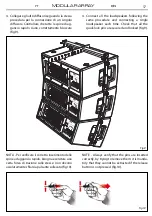
Page 17: ...rapido bisogna esercitare una certa forza di trazione sulle stesse non devono assolutamente sfilarsi a pulsante sollevato fig 10 4 Connect all the loudspeakers following the same procedure and connecting a single loudspeaker each time Check that all the quick lock pins are secured and locked fig 9 NOTE Always verify that the pins are inserted correctly by trying to remove them it is manda tory tha...

Page 18: ...lo po steriore del diffusore Poi agganciare la barra di sospensione al dispositivo di sollevamento fig 11 5 MA6BAR flying bar can be lifted using one of suspension points on the central support bracket Choose the appropriate hole posi tion according to the configuration tab on the rear panel of loudspeaker and fix the shackle to the flying bar Then connect the MA6BAR flying bar to the hoist connec...

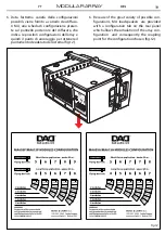
Page 19: ...e indica le possibili configurazioni dell array e quindi il punto di ancoraggio per ottenere il puntamento desiderato del sistema fig 12 6 Because of the great variety of possible con figurations MA loudspeakers are provided with a configuration tab on the rear panel which allows the simulation of the array con figuration and consequently the coupling point for the configuration chosen fig 12 Fig ...

Page 20: ...ortate di seguito alcuni esempi di confi gurazioni tipo 3 3 SUSPENDED CONFIGURATION MA modules for line array systems features two modules having different curvature MA605A MA605P HxV 80 x10 for long throw application MA615A MA615P HxV 100 x30 for short throw application The MA loudspeakers are designed for a wide range applications using from 2 up to six mod ules with a clear perspective to provi...

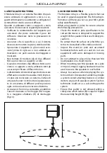
Page 21: ... possono agire come una vela e rovesciare il sistema Assicurarsi che non sia consentita al pubblico l area di sicurezza e che il raggio R sia ugua le o maggiore all altezza H di montaggio fig 13 3 4 GROUND MOUNTING The Modular Array is a flexible system that can be used in ground supported The following in formation will help you set up your MA system safely and effectively When using stands or po...

Page 22: ...feriore del diffusore In questo modo gli ascoltatori si troveranno all interno dell angolo di copertura 3 5 SINGLE MODULE A single MA may be used on a tripod stand or on a pole over its companion subwoofer the HD118SWA or the HD118SW fig 14 The use of a subwoofer is recommended for applications requiring more low frequency power and exten sion MA605 MA615 includes a dual angle 36 mm pole mount soc...

Page 23: ...zionare i diffusori sullo stand uno alla vol ta Bloccare i due diffusori insieme usando l har dware integrato fig 15 Non impilare più di due moduli MA su stativo 3 6 DUAL MODULE Unlike most conventional speakers the MA is de signed so that a pair of speakers may be safely mounted onto a pole or tripod stand For most applications the forward socket of the dual angle pole socket will be used 5 15 Th...

Page 24: ...ECTIONS AND CONTROLS 4 1 LOUDSPEAKER PANEL CONNECTION ACTIVE VERSION MA605A MA615A MAINS OUT MAINS IN MAINS IN MAINS OUT HIGH PASS F 4 6 UNIT HIGH PASS F FULL RANGE SIGNAL LIMIT PROTECT READY LINE OUT LINE IN PRESET SELECT TEMP 4dBu 8 MA605A MADE IN ITALY dad audio it Powered by 1 3 UNIT 4 6 UNIT 1 3 UNIT FULL RANGE Fig 16 ...

Page 25: ...PHASE 90Hz 120Hz 120Hz 90Hz MAINS OUT MAINS IN MAINS IN MAINS OUT LINE OUT LINE IN PRESET SELECT 4dBu 8 HD 118 SWA MADE IN ITALY dad audio it Powered by PANNELLO DI CONNESSIONE SUBWOOFER VERSIONE ATTIVA HD118SWA MA18SA SUBWOOFER PANEL CONNECTION ACTIVE VERSION HD118SWA HD118SWA MA18SA Fig 17 ...

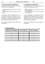
Page 26: ...t is completely disconnected from the power supply CONNESSIONI LINE IN Connettore XLR femmina che accetta XLR maschi da tutti gli apparecchi con un livello di uscita bilanciato Le terminazioni dell ingresso XLR sono Pin1 schermo o massa Pin2 positivo o caldo Pin3 negativo o freddo NOTA qualora possibile usare sempre cavi bi lanciati Cavi sbilanciati possono essere ugual mente usati ma potrebbero d...

Page 27: ...nuzione del livello sonoro nella regione interessata Una corretta rilevazio ne della fase per valutare se invertire il segnale dei subwoofer prevede l uso di un analizzatore di spettro CONTROLS MA605A MA615A FULL RANGE 1 3 UNIT This control reproduces a full range of frequencies For use where the low fre quencies are not required Configuration using 1 3 modules FULL RANGE 4 6 UNIT This control rep...

Page 28: ...empio120Hz REVERSE PHASE 120Hz NORMAL 90Hz REVERSE PHASE 90Hz NORMAL POTENZIOMETRO DI VOLUME Regola il livello del se gnale di uscita del diffusore LED INDICATORS LIMIT PROTECT Protect Function Red LED illuminates when the amplifier module is in protect mode for one of the following rea sons The heatsink reaches a temperature above the normal working limit There is a short circuit at the amplifier...

Page 29: ...ction to other passive loud speakers Connessioni Connections MA605P MA605P Connessioni Connections HD118SW MA18SP Fig 18 dad audio com HD118 SW Nominal Impedance 8 Ohm AES Program Power 1700 3400W 13061001 S N ISO 9001 2008 CERTIFIED COMPANY MUSIC LIGHTS ITALY DESIGN ENGINEERING musiclights it Made in ITALY INPUT LINK 2 2 2 2 2 2 2 2 1 1 1 1 MA 605P Nominal Impedance 8 Ohm AES Program Power 500 10...

Page 30: ...ei 300 Hz La funzione del filtro Cupling in relazione ai moduli impiegati è illustrata nel diagramma della figura TONAL BALANCE WITH DPX2060 PROCESSOR The array tonal balance depends in particu lar by the number of speakers that compose it At the same signal sent an array of few elements is lacking in midbass range as op posed to an array that consists of many units in which the midbass range is t...

Page 31: ...de Memory 9 1 2 FULLRANGE set up for 1 2 modules in full range configuration Memory 10 3 4 FULLRANGE set up for 3 4 modules in full range configuration Memory 11 5 6 FULLRANGE set up for 5 6 modules in full range configuration a DPX2060 AUDIO MANAGEMENT SYSTEM b c Fig 20 Memoria 5 3 4 CUT 90Hz set up per 3 4 mo duli in configurazione passa alto Memoria 7 5 6 CUT 90Hz set up per 5 6 mo duli in conf...

Page 32: ...iportato lo schema di collegamento del processore Fig 21 OUT6 OUT1 OUT2 OUT3 OUT4 OUT5 IN B IN A 100 230V 30W 50 60Hz RS232 MA18SP HD118SW MA605P MA615P MA615P MA605P MA18SP HD118SW In order to optimize the overall operation of the array each set up of DPX2060 processor in rela tion to the number of used modules expects the dedicated output at MA605 and MA615 modules The figure shows the wiring di...

Page 33: ...a scariche ecc sono dovuti unicamente all utilizzo di cavi inadatti o avariati 5 CONNECTION CABLES 5 1 INPUT CONNECTION To connect the mixer outputs to the amplifiers inputs make sure to always use balanced signal cables Unbalanced lines may also be used but may result in noise over long cable runs In any case avoid using a balanced cable for one chan nel and an unbalanced one for the other or a b...

Page 34: ... neutro fase e terra tipo B per uscita alimentazio ne POWER OUT 6 2 POWER SUPPLY CONNECTORS PowerCon NAC3FCA BLUE AC connector with 3 conductors neutral phase and ground Type A for power input MAINS IN PowerCon NAC3FCB GREY AC connector with 3 conductors neutral phase and ground Type B of power output POWER OUT ground hot cold ground hot cold INPUT ingresso XLR bilanciato maschio INPUT Balanced ma...

Page 35: ...er 2 6 coil High frequency 1 4 Nd driver 3 coil 1 4 Nd driver 3 coil 1 4 Nd driver 3 coil 1 4 Nd driver 3 coil Input sensitivity 4dBu 1 228Vrms 4dBu 1 228Vrms 101dB 1W 1m 100dB 1W 1m Max SPL Cont Peak 132 138dB Free field 131 137dB Free field 132 138dB Free field 131 137dB Free field Crossover frequency 1100Hz 1100Hz 1100Hz 1100Hz User controls Full range 1 3 4 6 High Pass Filter 1 3 4 6 Full rang...

Page 36: ...dB 35 150Hz 3dB Low frequency 18 Nd woofer 4 coil 18 Nd woofer 4 coil 18 Nd woofer 4 5 coil 18 Nd woofer 4 5 coil Input sensitivity 4dBu 1 228Vrms 97dB 1W 1m 4dBu 1 228Vrms 97dB 1W 1m Max SPL Cont Peak 128 134dB 128 134dB 128 134dB 128 134dB Suggested x over LPF processed 80 150Hz LPF processed 80 150Hz User controls 120Hz 90Hz normal Reverse phase 120Hz 90Hz normal Reverse phase Protection RMS li...

Page 37: ...0K 20K 15 5 10 0 5 10 15 20 25 30 35 dB FULL RANGE FULL RANGE 1 3 4 6 20 Hz 50 100 200 500 1K 2K 5K 10K 20K 15 5 10 0 5 10 15 20 25 30 35 dB HIGH PASS FILTER HIGH PASS FILTER 1 3 4 6 120Hz REVERSE PHASE NORMAL 90Hz REVERSE PHASE NORMAL 110 100 90 80 70 60 20 Hz 50 100 200 500 1K 2K 5K 10K 20K dB 110 100 90 80 70 60 20 Hz 50 100 200 500 1K 2K 5K 10K 20K dB ...

Page 38: ...ssono essere usati ma risulteranno rumorosi sulle lunghe distanze Talvolta può essere di aiuto alimentare tutto l equipaggiamento audio collegandolo dalla stessa linea di corrente AC in modo che tut ti gli apparati condividano la stessa presa di terra TROUBLESHOOTING No Power Make sure the mains AC outlet is live check with a tester or a lamp Make sure the mains plug is securely plugged into mains...

Page 39: ... in se rie o in parallelo Collegare in serie due altopar lanti significa unire un terminale positivo ed uno negativo dei due e collegare all amplificatore i BRIEF NOTES ON ACOUSTIC Diffusing sound into an environment means to distribute sound signals to a given audience and the results are dependent on several ambient factors room shape volume etc the number of the people present and their precise...

Page 40: ...sare un amplificatore con potenza RMS pari alla potenza AES del diffusore facendo comunque attenzio ne a non fornire un segnale di ampiezza tale da portare troppo spesso in clipping l amplifica ance value corresponds to the amplifier output impedance There are 2 possible connection systems serial or parallel mode Connecting two speakers in series means to connect the positive pole of the first spe...

Page 41: ...sensitivity as displayed on the master outputVU meter tore La potenza di breve termine IEC268 5 è la potenza che il diffusore può sopportare per un brevissimo intervallo di tempo Corrisponde a 4 volte la potenza AES e viene calcolata in base alla massima tensione di picco che l amplificato re consigliato può fornire al diffusore Le capa cità in termine di SPL nei transistori del segnale musicale s...

Page 42: ...utti ad esempio Ray Dolby RMS Root mean square rms La sigla si riferi sce al più comune metodo matematico atto a definire l effettivo voltaggio o corrente di un on da di corrente alternata Il nome deriva dal fatto che il valore ottenuto è la radice quadrata squa re root della media aritmetica dei quadrati dei valori Glossary SPL Sound pressure level is a logarithmic meas ure of the rms sound press...

Page 43: ...chi conseguenti sono a carico del possessore dell apparecchio A tutti gli effetti la validità della garanzia è avallata unicamente dalla presentazione del certificato di garanzia The guarantee covers the unit in compliance with existing regulations You can find the full version of the General Guarantee Conditions on our web site www musiclights it Abstract General Guarantee Conditions Please remem...

Page 44: ...date Data acquisto FORM TO BE FILLED IN AND MAILED CEDOLA DA COMPILARE E SPEDIRE FORM TO BE FILLED IN AND KEPT CEDOLA DA COMPILARE E CONSERVARE PROV ZIP CODE C A P MODEL MODELLO SERIAL N SERIE N Purchased by Acquistato da SURNAME COGNOME Dealer s stamp and signature Timbro e firma del Rivenditore NAME NOME ADDRESS VIA N CITY CITTà Purchasing date Data acquisto PROV ZIP CODE C A P ...

Page 45: ......

Page 46: ......

Page 47: ......

Page 48: ... r l DAD is a brand of Music Lights S r l company 2014 Music Lights S r l MUSIC LIGHTS S r l Via Appia km 136 200 04020 Itri LT ITALY Phone 39 0771 72190 Fax 39 0771 721955 www musiclights it email info musiclights it ISO 9001 2008 Certified Company ...

Reviews: