background image

16

Installation Instructions

Re-installing the Oven Door


wARNINg

To avoid personal injury or damage to the door from it 

falling off its hinges:

• 

Make sure that the notch on the bottom of each hinge rests 

on top of the lower lip of each hinge receptacle before 

attempting to open the oven door.

• 

Rotate the hinge locks toward the front of the range 

immediately after installation of the door.

1.  Grasp the oven door on opposite sides and hold it at a 15° 

angle from the front of the range. Slide the hinges into the 

hinge openings, resting the bottom of the hinge arms on the 

hinge receptacles. Continue to hold the door at a 15° angle 

with one hand while pushing in on each of the bottom corners 

of the door. Push until the notch on the bottom of each hinge 

slips over the lower lip of each hinge receptacle.

2.  Lower the door to the fully opened position.
3.  Rotate the two hinge locks toward the range.
4.  Slowly and carefully open and close the door completely to 

ensure that it is properly installed.

Installing the Range

Peel off the protective layer of plastic that covers the stainless 

steel surfaces.

Freestanding Installation

1.  Measure from the floor to the countertop and adjust the 

leveling legs as required to position the top frame at the 

desired height, based on the cabinet and countertop 

installation.

2.  Carefully slide the range into position in the cutout. As you 

slide the unit into place the rear leg should engage the anti-

tip bracket.

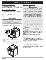
3.  Using a flashlight look underneath the range and verify that 

the anti-tip bracket covers the rear leg. See diagram below.

4.  Use a level to make sure that the range does not tilt front to 

back or side to side. Re-adjust the legs to level and change 

the height if necessary.

Self-Rimming Installation

Installation of the range in the self-rimming configuration is 

slightly different from freestanding installation since the range top 

overhangs the countertop cutout.
1.  Measure from the floor to the countertop.
2.  Adjust the leveling legs to position the bottom edge of the 

range top trim at countertop height.

3.  Carefully slide the range into position in the cutout. As you 

slide the unit into place the rear leg should engage the anti-

tip bracket.

4.  Using a flashlight look underneath the range and verify that 

the anti-tip bracket covers the rear leg. See diagram below.

5.  Use a level to make sure that the range does not tilt front to 

back or side to side. Re-adjust the legs to level and change 

the height if necessary.

Anti-tip 

bracket

Rear leg

Summary of Contents for Renaissance RR30NFS

Page 1: ...Installation Instructions Renaissance Electric Range Part No 105910 Rev A Models RR30NS RR30NS C RR30NFS RR30NFS C RR30NIS and RR30NIFS with induction cooktop...

Page 2: ...al number are printed on the product data label Dacor Customer Service Phone 800 793 0093 extension 2813 U S A and Canada Monday Friday 6 00 a m to 5 00 p m Pacific Time Web site www dacor com Dacor D...

Page 3: ...eath warning NEVER use this appliance as a space heater to heat or warm the room Doing so may result in overheating of the appliance warning NEVER cover any slots holes or passages in the oven bottom...

Page 4: ...iance is not approved for installation in a mobile home or recreational vehicle This appliance must not be used in combination with surface countertop ventilation systems The use of an overhead hood o...

Page 5: ...ion box or A 3 wire conduit where local code permits connected to a 3 wire junction box Suggested conduit wiring color code black white red and green Using an appliance cord A 4 wire appliance cord eq...

Page 6: ...piece in place of a backguard A backguard may be purchased as an optional accessory Add an additional 1 16 inch to the depth dimensions above when installing a backguard on models RR30NIS and RR30NIF...

Page 7: ...ications for minimum clearances If cabinet storage space is to be provided directly above the range the risk of personal injury may be reduced by installing a range hood The range may be installed flu...

Page 8: ...tion Models RR30NIS and RR30NIFS Only To create a built in look on the front of the cabinet this dimension may be changed to 29 1 4 74 3 cm with the width at the notches remaining 30 1 16 This configu...

Page 9: ...this dimension may be changed to 29 1 4 74 3 cm with the width at the notches remaining 30 1 16 This configuration is only for models RR30NIS and RR30NIFS with the side panels behind the door removed...

Page 10: ...quired The minimum full thread depth portion of screw threaded into wood slab for wood is 3 8 1 cm and 5 8 1 6 cm for concrete See the table below to select the correct screw size Sub Floor Type Floor...

Page 11: ...thod may not be used and the floor mounting method must be suitable or the wall must be modified so that the base plate is above the notches 4 To install the bracket place it against the wall in the m...

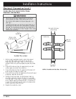
Page 12: ...ng can cause an electric shock hazard and damage the appliance Dacor is not responsible for damages resulting from improper installation This range must be connected to a grounded metallic permanent w...

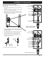
Page 13: ...relief inside the box Tighten into place 6 Connect the white wire to the neutral terminal inside the box 7 Connect the black wire to the L1 power supply terminal 8 Connect the red wire to the L2 powe...

Page 14: ...ce inside the junction box 2 Connect the white wire from the appliance to the neutral white supply wire inside the junction box 3 Connect the black wire from the appliance to the black L1 power supply...

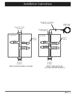
Page 15: ...Conduit Junction Box Connection with External Ground Separate No 10 minimum copper grounding wire Wire nut 4 places Conduit to appliance Conduit to appliance Wire nut 3 places Junction box Junction b...

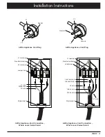
Page 16: ...onnection cont Appliance Cord Connections Where Local Code Permits warning Do not connect the green appliance wire to the neutral white supply wire unless local building codes permit 1 Remove the rang...

Page 17: ...umper link Link removed Ground screw L2 terminal L2 terminal L1 wire L1 wire White wire White wire Green wire L2 wire L2 wire Strain relief Strain relief 3 Wire Appliance Cord Connection Where Local C...

Page 18: ...loor to the countertop and adjust the leveling legs as required to position the top frame at the desired height based on the cabinet and countertop installation 2 Carefully slide the range into positi...

Page 19: ...e troubleshooting steps Verify that power is being supplied to the range Check the electrical connections to ensure that the installation has been completed correctly Repeat the above tests If the app...

Page 20: ...Dacor 14425 Clark Avenue City of Industry CA 91745 Phone 800 793 0093 Fax 626 403 3130 www dacor com...

Reviews: