E4
Design Specifications
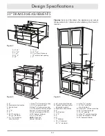
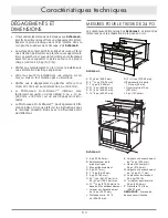
30" DRAWER MEASUREMENTS
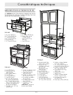
Figures 3, 4 and 5 contain the appliance and cutout
measurements for reference when planning the drawer’s
location.
A
B
C
D
E
F
G
H
I
I
J
K
L
M
N
0
P
A
B
C
L
K
J
D
E
G
H
F
I
M
M
N
O
P
Q
R
A
B
C
F
I
D
H
G
E
J
A. 21
5
/
8
"
B. 4
11
/
16
"
C. 1
3
/
4
"
D. 21
7
/
8
"
E. 30"
F. 15
7
/
8
"
G. 14
19
/
32
"
H. 1
9
/
64
" door thickness
I. 15" auto drawer opening
J. 4"
Figure 4
A. 6"
B. Electrical outlet location
C. Anti-tip block
D. 5"
E. 3
1
/
2
"
F. 4"
G. 22
1
/
8
" minimum
28
7
/
16
" maximum
H. 14
13
/
16
" to bottom
of anti-tip block
I. Allow
23
/
32
" minimum overlap
J. 23
1
/
2
" minimum depth
K. Allow
3
/
16
" minimum overlap
L. 36" nominal countertop height
M. Allow
1
/
8
" minimum overlap
N. Floor must support 100 lbs.
O. *30" cabinet minimum
P. 15
9
/
16
" opening
NOTE:
Open Top
Cabinet illustrated
Figure 5
A. 84" nominal wall cabinet
B. Optional wall oven cutout
illustrated in sketch
C. Electrical outlet location
D. 6"
E. Anti-tip block
F. 3
1
/
2
"
G. 5"
H. 4"
I. 2" minimum
J. 22
1
/
8
” minimum
28
7
/
16
” maximum
K. Allow
3
/
16
" overlap
L. 14
13
/
16
" to bottom
of anti-tip block
M. Allow
23
/
32
" minimum overlap
N. 23
1
/
2
" minimum depth
O. 15
9
/
16
" opening
P. Allow
1
/
8
" minimum overlap
Q. Floor must support 100 lbs.
R. 30" cabinet minimum
A
B
C
D
E
F
G
H
I
I
J
K
L
M
N
0
P
A
B
C
L
K
J
D
E
G
H
F
I
M
M
N
O
P
Q
R
A
B
C
F
I
D
H
G
E
J
A
B
C
D
E
F
G
H
I
I
J
K
L
M
N
0
P
A
B
C
L
K
J
D
E
G
H
F
I
M
M
N
O
P
Q
R
A
B
C
F
I
D
H
G
E
J
Figure 3


