background image

ENGLISH

15

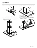
7.  Install the 4 vertical supports with 16 - 4.2 x 8 mm 

screws. 

A. 4 - Upper vertical supports

B.  16 - 4.2 x 8 mm screws

B

A

8.  Install the structure to the horizontal support with 

16 - 4.2 x 8 mm screws. 

A. Upper horizontal support

B.  16 - 4.2 x 8 mm screws

C.  Duct cover extension


B.

B.  

A

C

B

9.  Using 2 or more people, lift the hood assembly under 

the structure.

A

B

A. Lower vertical supports

B.  Hood assembly

10.  Attach the hood assembly to the lower vertical 

supports with 2 mounting screws.

A

C

B

A. 2 - Mounting 

screws

B.  Lower vertical 

support

C.  Place mounting 

screws through 

the structure

Installation

Summary of Contents for DHD U990I/DA Series

Page 1: ...LIB0180483 Installation Instructions Instructions d Installation Instrucciones para instalaci n Chimney Island Hood Hotte en lot Campana de isla DHD U990I DA...
Page 2: ...thods 8 Ducting options 9 What is in the box 10 Tools and parts 11 Dimetions and clearances 12 Accessories Sold Separately 12 Installation 12 Installation instructions 12 Ceiling support structures 13...
Page 3: ...this manual forpersonal and professional reference CustomerService To resolve questions and installation issues contact yourDacordealerorDacorcustomerservice Before calling have the hood s model and s...

Page 4: ...it in a safe place forfuture reference State of California Proposition 65 warning US only WARNING This product contains chemicals known to the State of California to cause cancerand birth defects oro...

Page 5: ...Forproducts sold in the US and Canadian markets only channels1 11 are available You cannot select any otherchannels IC RADIATION EXPOSURE STATEMENT This equipment complies with IC RSS 102 radiation ex...

Page 6: ...IRE OBSERVE THE FOLLOWING PRECAUTIONS SMOTHER FLAMES with a close fitting lid cookie sheet ormetal tray then turn off the burner BE CAREFUL TO PREVENT BURNS If the flames do not go out immediately EVA...

Page 7: ...ey Road Cleveland OH 44131 5575 A120 volt 60 Hz AC only 15 amp fused electrical circuit is required If the house has aluminum wiring follow the procedure below 1 Connect a section of solid copperwire...

Page 8: ...its the house Hood must be vented to the outside of building only Discharge direction This hood is factory set forventing through the roof vertical discharge orwall horizontal discharge To vent throug...

Page 9: ...nce with the type of wall ceiling Before making cutouts make sure there is proper clearance within the ceiling orwall forthe exhaust vent Mounting Height CAUTION Mount this hood so that the bottom edg...

Page 10: ...e fan Uppervertical supports 4 Lowervertical supports 4 36 single fan Hood base 1 42 double fan 54 double fan Blowerhousing with 10 transition 1 42 double fan 54 double fan Horizontal support 1 42 dou...

Page 11: ...5 mm 2 Torx adapter 10 Single fan model 1 20 Single fan model 1 20 Double fan model 1 Mounting screws 2 Mounting template 1 Parts not supplied Tools materials required Level Drill with 4 76 mm drill b...

Page 12: ...tall the hood It is the installer s responsibility to ensure the hood complies with the installation clearances specified forthe product It is recommended that the vent system be installed before the...

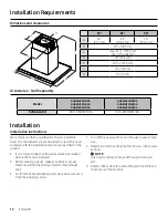
Page 13: ...tallations At the hood location install 2 x 4 cross framing between ceiling joists as shown 2 x 4 are required to support the weight of the hood Arrange cross framing in the ceiling to suit the existi...

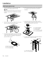
Page 14: ...using the Torx 20 adapter That will be the upperhorizontal support C B C A A Upperhorizontal support B Duct coverextension C 4 4 2 x 8 mm screws 4 Fix the upperhorizontal support to the ceiling with 4...

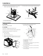
Page 15: ...m screws A Upperhorizontal support B 16 4 2 x 8 mm screws C Duct coverextension B B A C B 9 Using 2 ormore people lift the hood assembly under the structure A B A Lowervertical supports B Hood assembl...

Page 16: ...EATH OR ELECTRICAL SHOCK 1 Disconnect power 2 Remove terminal box cover 3 Remove the knockout in the terminal box coverand install a UL listed orCSA approved strain relief B A A Knockout B Terminal bo...

Page 17: ...l the double fan hood 1 Place the template in the ceiling considering the instructions forceiling support structures NOTE Always considerthe front of hood when placing the template on the ceiling It w...

Page 18: ...he blowerhousing under the structure A B A Vertical supports B Blowerhousing 7 Attach the blowerhousing to the vertical supports with 2 mounting screws C A B A 2 Mounting screws B Vertical support C P...

Page 19: ...motorhousing Insert the hood base pins into the housing lowerslots Once the fourpins are inserted the hood base is supported 11 Secure the hood base to the blowerhousing with 4 4 2 x 8 mm screws A Ho...

Page 20: ...ome powersupply cable B UL listed orCSA approved strain relief C Black wires D UL listed wire connectors E White wires F Green orbare and yellow green ground wires A D B E C F 5 Use UL listed wire con...

Page 21: ...slots B using the Torx10 adapter NOTE The slotted holes in the upperduct covers will be visible when assembled and can be hidden down inside the lowerduct covers A B A Upperduct covers B 2 3 5 x 6 5...

Page 22: ...the filterinto the hood 2 Push up on the back the handle and then set rearof filterinto the drip tray to secure Repeat foreach filter 1 2 Model shown forreference only features mayvary To get the mos...

Page 23: ...duct cover Ductcover NOTE The nameplate badge hasveryhigh retention adhesive once the nameplate badge is attached its extremelydifficult to remove Before removing the release paperfrom the back of th...

Page 24: ...que contient la bo te 32 Outils et pi ces 33 Dimentions et d gagements 34 Accessoires Vendus s par ment 34 Installation 34 Instructions d installation 34 Structures de support des plafonds 35 Install...

Page 25: ...r f rer titre personnel et professionnel Service la client le Pourr soudre les questions et les probl mes d installation contactez votre revendeurDacorou le service client Dacor Avant d appeler muniss...

Page 26: ...n endroit s rpourpouvoirla consulterult rieurement State of California Proposition 65 warning US only AVERTISSEMENT Ce produit contient des produits chimiques connus dans l tat de Californie pourprovo...

Page 27: ...rme ICES 003 du Canada Pourles produits vendus surles march s am ricain et canadien seuls les canaux1 11 sont disponibles Vous ne pouvez pas s lectionnerd autres canaux D CLARATION D EXPOSITION AUX RA...

Page 28: ...surface AVERTISSEMENT AFIN DE R DUIRE LE RISQUE DE BLESSURES AUX PERSONNES EN CAS DE FEU DE GRAISSE SUR LE DESSUS DE LA CUISINI RE OBSERVEZ LES PR CAUTIONS SUIVANTES SMOTHER FLAMES with a close fitti...

Page 29: ...seulement 15 amp res avec fusible est n cessaire Si la maison a un c blage en aluminium suivez la proc dure suivante 1 Connectez une section de fil de cuivre solide aux fils de la queue de cochon 2 Co...

Page 30: ...coude de 90 est n cessaire Installez toujours un couvercle d vent m tallique l endroit o les conduits sortent de la maison La hotte doit tre ventil e uniquement l ext rieurdu b timent Direction de la...

Page 31: ...oupes assurez vous qu il y a un d gagement appropri dans le plafond ou le murpourle conduit d vacuation Hauteurde montage ATTENTION Montez cette hotte de fa on ce que le bord inf rieurau dessus de la...

Page 32: ...4 Supports verticaux inf rieurs 4 36 ventilateurunique Tiroir hotte 1 42 ventilateurdouble 54 ventilateurdouble Bo tierdu moteur du ventilateuravec transition de10 1 42 ventilateurdouble 54 ventilateu...

Page 33: ...2 AdaptateurTorx 10 Mod le ventilateurunique 1 20 Mod le ventilateurunique 1 20 Mod le double ventilateur 1 Vis de montage 2 Gabarit de montage 1 Pi ces non fournies Outils Mat riaux requis Niveau Per...

Page 34: ...uit Il est recommand d installerle syst me de ventilation avant d installerla hotte Si possible d branchez et retirez tout appareil de cuisson situ sous la hotte pourfaciliterl acc s la paroi arri re...

Page 35: ...e la hotte installez une charpente transversale de 2 po x 4 po entre les solives du plafond tel qu illustr 2 po x 4 po sont n cessaires poursupporterle poids de la hotte Disposez l ossature transversa...

Page 36: ...2 x 8 mm en utilisant l adaptateurTorx 20 Ce sera le support horizontal sup rieur C B C A A Support horizontal sup rieur B Extension du couvercle de la gaine C 4 4 2 x 8 mm vis 4 Fixez le support hori...

Page 37: ...t horizontal sup rieur B 16 4 2 x 8 mm vis C Extension du couvercle du conduit B B A C B 9 l aide de 2 personnes ou plus soulevez l ensemble de la hotte sous la structure A B A Supports verticaux inf...

Page 38: ...ez l alimentation 2 Retirerle couvercle de la bo te bornes 3 Retirerla d bouchure du couvercle de la bo te bornes et installerune d charge de traction homologu e UL ou CSA B A A D bouchure B Couvercle...

Page 39: ...lerla hotte double ventilateur 1 Placez le gabarit dans le plafond en tenant compte des instructions relatives aux structures de support du plafond REMARQUE Tenez toujours compte de l avant du capot l...

Page 40: ...oulevez le bo tier du ventilateursous la structure A B A Supports verticaux B Bo tierdu ventilateur 7 Fixez le bo tierdu ventilateuraux supports verticaux l aide de 2 vis de montage C A B A 2 Vis de m...

Page 41: ...es du tiroirde la hotte dans les fentes inf rieures du bo tier Lorsque les quatre goupilles sont d j ins r es le tiroirde la hotte se tient support 11 Fixez le tiroirde la hotte au bo tierdu ventilate...

Page 42: ...anti traction A C ble d alimentation domestique B Serre fils r pertori UL ou approuv CSA C Fils noirs D Connecteurs de fils r pertori s UL E Fils blancs F Fils de terre verts ou nus et jaune vert A D...

Page 43: ...UE Les trous oblongs des couvercles des gaines sup rieures seront visibles lors de l assemblage et peuvent tre cach s l int rieurdes couvercles des gaines inf rieures A B A Couvercles des gaines sup r...

Page 44: ...oign e puis placez l arri re du filtre dans le plateau d gouttement pourle fixer R p tez l op ration pour chaque filtre 1 2 Mod le pr sent titre de r f rence uniquement caract ristiques peuvent varier...

Page 45: ...adh sif Garbarit Partie inf rieure de la couvercle de gaine Couvercle de conduit NOTE The nameplate badge hasveryhigh retention adhesive once the nameplate badge is attached its extremelydifficult to...

Page 46: ...en la caja 54 Herramientas y piezas 55 Dimensiones y espacios libres 56 Accessorios Se vende porseparado 56 Instalaci n 56 Instrucciones de instalaci n 56 Estructuras de soporte del techo 57 Instalac...

Page 47: ...icio de Atenci n al Cliente Para resolverdudas y problemas de instalaci n p ngase en contacto con su distribuidorDacoro con el servicio de atenci n al cliente de Dacor Antes de llamar tenga a mano el...

Page 48: ...oducto contiene sustancias qu micas conocidas porel Estado de California como causantes de c ncery defectos de nacimiento u otros da os reproductivos www p65warnings ca gov 1 Noticia de la FCC PRECAUC...

Page 49: ...on la norma canadiense ICES 003 Para los productos vendidos en los mercados estadounidense y canadiense s lo est n disponibles los canales1 11 No se puede seleccionarning n otro canal DECLARACI N DE E...

Page 50: ...ma o de la superficie del element ADVERTENCIA PARA REDUCIR EL RIESGO DE LESIONES A LAS PERSONAS EN CASO DE INCENDIO DE LA GRASA DE LA ENCIMERA OBSERVE LAS SIGUIENTES PRECAUCIONES APAGUE LAS LLAMAS con...

Page 51: ...ctrico de120 voltios 60 Hz s lo CA 15 amperios con fusible Si la casa tiene cableado de aluminio siga el procedimiento siguiente 1 Conecte una secci n de cable de cobre s lido a los cables flexibles 2...

Page 52: ...n en el lugardonde los conductos salen de la casa La campana debe ventilarse nicamente hacia el exteriordel edificio Direcci n de descarga Esta campana viene ajustada de f brica para ventilar a trav...

Page 53: ...los recortes aseg rese de que existe un espacio libre adecuado dentro del techo o la pared para la ventilaci n del escape Altura de montaje PRECAUCI N Monte esta campana de manera que el borde inferio...

Page 54: ...tes verticales inferiores 4 36 ventiladorindividual Base de la campana 1 42 doble ventilador 54 doble ventilador Carcasa del motordel ventiladorcon transici n de10 1 42 doble ventilador 54 doble venti...

Page 55: ...ladorindividual 1 20 Ventiladorindividual 1 20 Doble ventilador 1 Tornillos de montaje 2 Plantilla de montaje 1 Piezas no suministradas Herramientas materiales necesarios Nivel Taladro con 4 76 mm de...

Page 56: ...de que la campana extractora cumple con las distancias de instalaci n especificadas para el producto Se recomienda instalarel sistema de ventilaci n antes de instalarla campana Antes de hacerlos recor...

Page 57: ...la ubicaci n de la campana instale un marco transversal de 2 x 4 entre las vigas del techo como se muestra se requieren 2 x 4 para soportarel peso de la campana Disponga el entramado transversal del...

Page 58: ...l adaptadorTorx 20 Ese ser el soporte horizontal superior C B C A A Soporte horizontal superior B Extensi n de la tapa del conducto C 4 tornillos de 4 2 x 8 mm 4 Fije el soporte horizontal superioral...

Page 59: ...llos de 4 2 x 8 mm C Extensi n de la tapa del conducto B B A C B 9 Con la ayuda de 2 o m s personas levante el conjunto de la campana extractora pordebajo de la estructura A B A Soportes verticales in...

Page 60: ...1 Desconecte la alimentaci n 2 Retire la tapa de la caja de terminales 3 Retire el orificio ciego de la tapa de la caja de terminales e instale un alivio de tensi n de aprobado porUL o CSA B A A Knock...

Page 61: ...mentaci n Instalarla campana extractora de doble ventilador 1 Coloque la plantilla en el techo teniendo en cuenta las instrucciones para las estructuras de soporte del techo NOTA Tenga siempre en cuen...

Page 62: ...sa del sopladorpordebajo de la estructura A B A Soportes verticales B Carcasa del soplador 7 Fije la carcasa del sopladora los soportes verticales con 2 tornillos de montaje C A B A 2 Tornillos de mon...

Page 63: ...s pasadores de la base de la campana en las ranuras inferiores de la carcasa Una vez introducidos los cuatro pasadores la base de la campana est soportada 11 Fije la base de la campana a la carcasa de...

Page 64: ...l hogar B Alivio de tensi n aprobado porUL o CSA C Cables negros D Conectores de cables homologados porUL E Hilos blancos F Hilos verdes o desnudos y amarillo verde de tierra A D B E C F 5 Utilice con...

Page 65: ...NOTA Los agujeros ranurados en las cubiertas de los conductos superiores ser n visibles cuando se ensamblen y pueden ocultarse dentro de las cubiertas de los conductos inferiores A B A Tapas del cond...

Page 66: ...te trasera del asa y a continuaci n coloque la parte trasera del filtro en la bandeja de goteo para asegurarlo Repita la operaci n con cada filtro 1 2 El modelo mostrado es s lo de referencia caracter...

Page 67: ...dhesivo Plantilla Parte inferior de la cubierta del ducto Cubierta del ducto NOTE The nameplate badge hasveryhigh retention adhesive once the nameplate badge is attached its extremelydifficultto remov...

Page 68: ...If you have any questions orcomments relating to Dacorappliances please contact the DacorCustomerService Center Country Contact Center Web Site U S A 1 833 353 5483 www dacor com CANADA 1 844 509 4659...

Reviews: