background image


ENGLISH 


86 


6.6.15.5  Setting low pressure detection (KIWA) 

The minimum pressure switch that detects low pressure can be connected to any input (for electrical connections, 
refer to paragraph 2.3.3). 

The low pressure detecting function is obtained by setting the parameter Ix, for the input to which the enabling signal 
has been connected, on one of the values in Tabella 26. 


Activation of the low pressure detection function generate a system block after time T1 (see T1: Tempo di 
spegnimento dopo il segnale bassa pressione  par. 6.6.2). This function is envisaged to connect the input to a signal 
from a pressure switch that indicates excessively low pressure on pump intake.  
When this function is enabled, the symbol F4 is shown on the STATUS line of the main page. 


When in the F4 error condition, the input must be deactivated for at least 2 seconds before the system unblocks. The 
function behaviour is summarised in Table 26. 
When several low pressure detection functions are configured at the same time on different inputs, the system 
indicates F4 when at least one function is activated and clears the alarm when none are activated. 


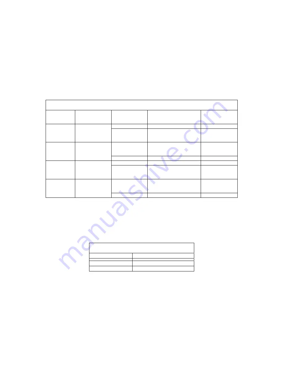
Response of system enable and fault reset function according to setting of INx and input 

Parameter 

value 

INx 

Input 

configuration 

Input status 

Operation 

Display 


10 

Active with high 

signal on input 

(NO) 


Absent Normal  None 

Present 

System block due to low 

pressure on intake; 

aut manual reset 

F4 

11 

Active with low 

signal on input 

(NC) 

Absent 

System block due to low 

pressure on intake; 

aut manual reset 

F4 

Present Normal  None 

12 

Active with high 

signal on input 

(NO) 


Absent Normal  None 

Present 

System block due to low 

pressure on intake. 

 Manual reset 

F4 

13 

Active with low 

signal on input 

(NC) 

Absent 

System block due to low 

pressure on intake. 

 Manual reset 

F4 

Present Normal  None 


Table 26: Low pressure signal detection (KIWA) 


6.6.16  Setup of outputs OUT1, OUT2  

This section illustrates the functions and possible configurations of the outputs OUT1 and OUT2 via parameters O1 
and O2.  
For electrical connections, see par. 2.3.4. 
The default settings are those in Table 27. 


Default output settings   

Output Value 

OUT 1 

2 (fault NO closes) 

OUT 2 

2 (Pump running NO closes) 

Table 27: Default output settings 

6.6.16.1  O1: Output 1 function setting  

Output 1 notifies of an active alarm (i.e. that there is a system block). The output enables use of a normally closed or 
normally open voltage-free contact.  
Parameter O1 is associated with the values and functions specified in Table 28. 


6.6.16.2 O2: Output 2 function setting 

Output 2 notifies of electric pump running status (pump on/off). The output enables use of a normally closed or 
normally open voltage-free contact.  
Parameter O2 is associated with the values and functions specified in Table 28. 


Summary of Contents for ACTIVE DRIVER PLUS M/M 1.1

Page 1: ...ENIMIENTO INSTALLATIONS OCH UNDERH LLSANVISNING KURMA VE BAKIM B LG LER N VOD NA IN TAL CIU A DR BU INSTRUCTIUNI PENTRU INSTALARE SI INTRETINERE INSTRU ES PARA A INSTALA O E A MANUTEN O ASENNUS JA HUO...

Page 2: ...ara las versiones firmware 1 x ES Bruksanvisning f r programvaruversioner 1 x SE firmware 1 x GR Donan m yaz l m n n 4 x 1 x versiyonlar i in ge erli el kitab TR Pr ru ka platn per verzie firmware 1 x...

Page 3: ...age 47 FRAN AIS page 93 DEUTSCH seite 140 NEDERLANDS pag 187 ESPA OL p g 234 SVENSKA sid 280 325 T RK E sf 372 SLOVENSKO stran 418 464 ROM N pag 512 PORTUGU S pag 558 SUOMI sivu 604 POLSKI strona 649...

Page 4: ...2 3 5 Abilitazione disabilitazione motore 22 4 SISTEMA MULTI INVERTER 23 4 1 Introduzione ai sistemi multi inverter 23 4 2 Realizzazione di un impianto multi inverter 23 4 2 1 Comunicazione 23 4 2 2 S...

Page 5: ...a pressione 32 6 4 3 C1 Visualizzazione della corrente di fase 32 6 4 4 PO Visualizzazione della potenza assorbita 32 6 4 5 RT Impostazione del senso di rotazione 32 6 4 6 VF Visualizzazione del fluss...

Page 6: ...BBRICA 44 8 1 Reset generale del sistema 44 8 2 Impostazioni di fabbrica 44 8 3 Ripristino delle impostazioni di fabbrica 44 9 Aggiornamento del firmware 46 9 1 Generalit 46 9 2 Aggiornamento 46 INDIC...

Page 7: ...one degli ingressi 14 Figura 3 Connessione delle uscite 15 Figura 4 Connessione della comunicazione multi inverter 16 Figura 5 Primo adescamento 16 Figura 6 Aspetto dell interfaccia utente 17 Figura 7...

Page 8: ...68 3 5 Enabling and disabling the motor 69 4 MULTI INVERTER SYSTEM 69 4 1 Introduction to multi inverter systems 69 4 2 Setting up a multi inverter system 69 4 2 1 Communication 69 4 2 2 Remote sensor...

Page 9: ...f the power delivered 78 6 4 5 RT Setting the direction of rotation 78 6 4 6 VF Flow display 78 6 5 Installer menu 78 6 5 1 RC Electric pump rated current setting 78 6 5 2 RT Setting the direction of...

Page 10: ...to reset of error conditions 89 8 RESET AND FACTORY SETTINGS 90 8 1 General system reset 90 8 2 Factory settings 90 8 3 Restoring the factory settings 90 9 Firmware update 92 9 1 General 92 9 2 Update...

Page 11: ...n 56 Figure 2 Input connection 60 Figure 3 Output connection 61 Figure 4 Connection of the multi inverter communication 62 Figure 6 Appearance of the user interface 63 Figure 7 Drop down menu selectio...

Page 12: ...Installation and operation must comply with the local safety regulations in force in the country in which the product is installed Everything must be done in a workmanlike manner Failure to respect t...

Page 13: ...ards Mains and motor terminals may carry dangerous voltage even when the motor is stopped In specific calibration conditions after a power failure the converter may start automatically Do not operate...

Page 14: ...Hz 50 60 50 60 50 60 50 60 50 60 50 60 50 60 Absorbed current Arms 10 22 9 16 10 13 17 Leakage current to earth mA 2 2 16 16 2 2 2 Electro pump Output Number of phases 3 3 3 3 1 1 1 Voltage VAC 3 x 22...

Page 15: ...1 female Functiona lity and prote ctions Connectivity CAN CAN CAN CAN CAN CAN CAN Dry operation protection YES YES YES YES YES YES YES Overload protection to electropump YES YES YES YES YES YES YES P...

Page 16: ...al to the loss of load caused by the filter itself generally the greater the filtering power the greater the fall in performance 2 1 Hydraulic connection The Inverter works at constant pressure This r...

Page 17: ...system each pump has its own delivery to its own inverter and the hydraulic outputs of the inverter all flow into a single manifold The manifold must be correctly sized to support the flow created by...

Page 18: ...or on the terminal board of the electropump 2 2 2 Pump connection for M M models The output for the electropump is available on the single phase cable earth indicated with the PUMP label Type DV inver...

Page 19: ...inverter is already equipped with internal safety devices the installation of a suitably sized thermal magnetic circuit breaker is recommended 2 3 2 Connection to the power supply for T T models The...

Page 20: ...rrent at 50 60 Hz In type M M the input can be activated only with a clean contact inserted between the two pins The wiring diagram and the electrical characteristics of the inputs are shown below Wir...

Page 21: ...blocks and the F3 signal is given ex IN 3 could be connected to a safety pressure switch with manual reset Power supply direct voltage Max 36V or alternating voltage Max 24Vrms Power supply direct vo...

Page 22: ...contact NO Max admissible voltage V 250 Max admissible current A 5 resistive load 2 5 inductive load Table 8 Output contact specifications 2 3 5 Connection of the remote sensor Connection of the remot...

Page 23: ...thers can be set by the user There are many other operating modes and accessory functions Thanks to the different possible settings and the availability of configurable input and output channels it is...

Page 24: ...matically after time T2 once the switching off conditions are reached T2 can be set by the user factory value 10 sec 3 KEYBOARD AND DISPLAY Figure 5 Appearance of the user interface The machine interf...

Page 25: ...the menus you can access the other menus by a combination of keys From the main menu you can also access the other menus from the drop down menu 3 2 1 Direct access with button combinations The menu...

Page 26: ...switch off PO Power absorbed by the pump FF Fault Warning Log P3 Auxiliary pressure 3 PO Power absorbed by the pump UN Rated voltage GP Proportional gain PI Power histogram CT Contrast RT Direction of...

Page 27: ...enus accessible one of which is highlighted with a bar see Figure 7 The buttons and can be used to move the highlighter bar to the menu required which is then entered by pressing SET Figure 6 Drop dow...

Page 28: ...es on functions associated with inputs Special icons The error or status conditions visible in the main menu are listed in Table 14 Error and status conditions visible in the main menu Identifier Desc...

Page 29: ...P3 are limited by SX SX is subordinate to the password The password management system is located in the menu technical assistance and is managed by means of parameter PW see paragrap 6 6 20 BP1 Block...

Page 30: ...rter and another otherwise the inverters may read different pressures from each other and give as a result a false mean value and an abnormal regulation For the operation of the booster set the invert...

Page 31: ...es these must all be different List of local parameters for inverters CT Contrast FP Test frequency in manual mode RT Direction of rotation AD Address IC Reserve configuration RF Fault and warning res...

Page 32: ...abled the first inverter starts and when this reaches maximum frequency the next one starts and so on The order of start up is not necessarily ascending according to the machine address but depends on...

Page 33: ...ere are 3 inverters and one of these is configured as reserve the reserve unit will start in third place otherwise if set to NA 2 the reserve will not start up unless one of the two active units sets...

Page 34: ...tion allowing a load beyond the safety threshold of the motor and causing damage to the motor 5 2 7 Setting the direction of rotation RT This parameter is present in all sizes of type M T and T T inve...

Page 35: ...ccording to the type of connection star or delta as stated on the motor dataplate see 6 5 1 2 Check that the motor has all phases connected 3 Check that the impeller or motor is not blocked or obstruc...

Page 36: ...level On the horizontal axis are the bars at the various power levels on the vertical axis the time for which the pump has been on at the specific power level of the time with respect to the total Th...

Page 37: ...The faults are shown in chronological order starting from the oldest x 1 to the most recent x y The maximum number of faults displayable is 64 after which the system overwrites the oldest versions in...

Page 38: ...Not available on type M M inverters The pump restart pressure depends both on the set pressure SP P1 P2 P3 and RP RP expresses the reduction in pressure with respect to SP or an auxiliary pressure if...

Page 39: ...ay or use the buttons or in the selection menu This menu enables the display and modification of various configuration parameters The MODE button enables the user to scroll through the menu pages whil...

Page 40: ...start This shows the drop in pressure with respect to the value SP which causes pump restart For example if the setpoint pressure is 3 0 bar and RP is 0 5 bar the pump is restarted at 2 5 bar RP is no...

Page 41: ...supply One example is that of a system where the electric pump intake line is particularly long and is subject to small leaks In this case it may occur that the pipeline empties and even if the water...

Page 42: ...ue other than N is entered the system sets to the maximum number of inverters that can be involved in pumping This parameter is used when there is a limited number of pumps to be kept in operation and...

Page 43: ...reserve is started up when another of the three including the first reserve has a fault 6 6 9 ET Exchange time This sets the maximum continuous operating time of an inverter within a group It is only...

Page 44: ...re could be some pressure increasing in the system thus the starting frequency must be close to the rated one for a while in a single phase pump to enable its turn on see sections 6 6 17 and 6 6 18 ea...

Page 45: ...is obtained by setting the parameter Ix for the input to which the float signal has been connected on one of the values in Tabella 23 Activation of the external float function generates a system bloc...

Page 46: ...g the system enable and fault reset The signal that enables the system can be supplied from any input for electrical connections refer to paragraph 2 3 3 The system enabling function is obtained by se...

Page 47: ...on Display 10 Active with high signal on input NO Absent Normal None Present System block due to low pressure on intake automatic manual reset F4 11 Active with low signal on input NC Absent System bl...

Page 48: ...it its normally the best for most of the pumps In any case ST can be changed between 0 and 3 secs When Ft 0 secs frequency will be immediately managed by PI and the pump will turn on at the rated freq...

Page 49: ...e of the fault must be located and eliminated Alarm in fault log Display message Description PD Irregular shutdown FA Problems with cooling system Table 29 Allarms Block conditions Display message Des...

Page 50: ...ay be due to voltage surges or excessively brusque shutdown of the pump 7 2 5 SC Block due to direct short circuit between the phases on the output terminal The inverter is equipped with a protection...

Page 51: ...Table 31 Auto reset of blocks 8 RESET AND FACTORY SETTINGS 8 1 General system reset To reset the system hold down the 4 keys simultaneously for 2 sec This operation is the same as disconnecting the p...

Page 52: ...Maximum setpoint bar 9 9 for size 4 7A 13 for size 10 5A 13 TB Delay for water failure block s 10 10 10 T1 Shutdown delay s 2 2 2 T2 Shutdown delay s 10 10 10 GP Proportional gain coefficient 0 6 0 6...

Page 53: ...heir own installed firmware The pop up allows you to proceed with the update by pressing on any one of the inverters The firmware update is carried out simultaneously on all the connected inverters th...

Page 54: ......

Page 55: ......

Page 56: ...x 32 2 4669218 DAB PUMPS IBERICA S L Avenida de Castilla nr 1 Local 14 28830 San Fernando De Henares Madrid Spain info spain dwtgroup com Ph 34 91 6569545 Fax 34 91 6569676 DAB PUMPS INC 3226 Benchmar...

Reviews: