background image


V019231_14_Rad-DX_Manual.docx 


Page 14 of 19 


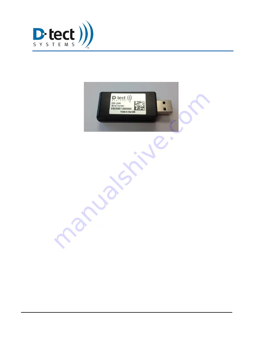
DX-Link 

The DX-Link is a small wireless USB communication device designed to facilitate mesh 
communication with one or more Rad-DX detectors.   


Figure 9: DX-Link 

The DX-Link’s USB interface allows for multiple uses such as improving the strength of your 
Mesh network and improving communications with Rad-DX detectors. Below is an explanation 
for each use-case scenario. 

6.1.1  Replace USB Cable 

The DX-Link provides a direct communication link between a PC and a Rad-DX detector, thus 
eliminating the need to monitor and adjust the settings of a detector with the use of a USB 
cable. Please note that using a DX-Link to replace the USB cable can only be used with the DX-
View software—not the DX-Dashboard software. 

6.1.2  Gateway to PC using DX-View 

The DX-Link can be used as a “gateway” while using the DX-View to monitor one or several 
Rad-DX detectors. If the DX-Link is inserted into a USB port on the PC, not only can you 
monitor, control, and download data from any Rad-DX detector as stated above, you can also 
view all detectors within the Mesh network. 

In the same manner that a DX-Link can act as a gateway, a Rad-DX that is connected to a PC 
via a USB cable can also act as a gateway. Again, this can only be done using the DX-View on 
your PC. 

6.1.3  Use as a Repeater 

The DX-Link can also be used as a “repeater” to improve the range of a Mesh network. When 
one detector is out of range of the Mesh network, a DX-Link can be strategically placed 
between that detector and another detector that is within range, providing a path of 
communication. The DX-Link can be used as a repeater in both the DX-Dashboard and DX-
View software. 

Summary of Contents for rad-DX

Page 1: ...AND OPERATING INSTRUCTIONS FOR THE RADIATION DETECTION SYSTEM Including Version 14 January 2017 D tect Systems Group Visionary Products Inc 11814 South Election Road Suite 200 Draper UT 84020 www dtec...

Page 2: ...9 3 1 1 DX View Software 9 3 1 2 DX Dashboard Software 9 3 1 3 DX Assistant Network Server 9 3 2 Using the LCD Screen 10 3 2 1 Explanation of Networking Icons on the LCD Touch Screen 11 4 Turning Off...

Page 3: ...rt of a larger Rad DX network for monitoring areas such as buildings or other facilities 2 Installation and Configuration 2 1 System Components There are several configurations available for Rad DX sy...

Page 4: ...1_14_Rad DX_Manual docx Page 4 of 19 Mounting Bracket USB Cable Wire Nuts and Mounting Screws Pigtail Wire Harness Power Cable black or white depending on color of Rad DX Table 1 Additional Rad DX Har...

Page 5: ...the installer 1 Mount the Rad DX wall bracket onto the junction box using the screws included If a non standard junction box is being used connect the wall bracket to the wall with drywall anchors or...

Page 6: ...Mount the Rad DX wall bracket to the wall using drywall anchors or wood screws 2 Connect the A C power cord to the Rad DX Then plug this cord into a nearby outlet Note The plug in wall method is meant...

Page 7: ...losure also offers additional features to improve performance including two larger higher gain antennas a cooling fan and a larger longer lasting backup battery The option to include the NEMA enclosur...

Page 8: ...ure for the detector Larger High Gain Antennas The standard Rad DX has two built in antennas one for Wi Fi and the other for Mesh communication The NEMA enclosure option comes with two larger higher g...

Page 9: ...s a web server application which can be used to monitor and control a Rad DX network remotely It runs on either the D tect Cloud Server or on the DX Network Assistant if installed at your facility Usi...

Page 10: ...Screen will appear on the LCD screen after the booting sequence is complete 4 The red lines shown below indicate the touch zone areas for each screen Reset the dose to zero by touching Total radiation...

Page 11: ...rking Icons on the LCD Touch Screen The appearance of any network connection icon indicates that the device is currently connected via the referenced connection Wi Fi Connection Battery Level USB Conn...

Page 12: ...ice will turn off If the power cable is still connected then the device will power cycle and turn back on The third method is to press and hold the battery icon located in the upper left hand corner o...

Page 13: ...x 272 Touch Screen Units Rem hr Sv hr CPS Audible Alarm Piezoelectric buzzer with LCD Display version only Alarm Volume 98dB Humidity 95 non condensing Dimensions 5 97 x 5 92 x 1 75 15 2 cm x 15 cm x...

Page 14: ...DX Dashboard software 6 1 2 Gateway to PC using DX View The DX Link can be used as a gateway while using the DX View to monitor one or several Rad DX detectors If the DX Link is inserted into a USB p...

Page 15: ...n if the DX Link and the computer are not communicating Figure 10 Sample USB Power Adapter Figure 11 DX Link as a Repeater You can now extend the range of communication between the Rad DX and the moni...

Page 16: ...partie responsible de la conformit ont pu vider I autorit de I utilisateur pour actioner cet equipment This Class B digital apparatus complies with Canadian ICES 003 Cet appareil num rique de la class...

Page 17: ...20cm between the radiator and your body Note Importante Pour l utilisation de dispositifs mobiles Declaration d exposition aus radiations Cet quipement est conforme aux limites d exposition aux rayon...

Page 18: ...approved by the customer that are not included in either the Limited or Extended Warranty these services will be billed to the customer at D tect Systems standard prices and terms D tect Systems does...

Page 19: ...become or in D tect System s opinion be likely to become the subject of a claim of infringement of a United States patent that you will permit D tect Systems at its option and expense either to procu...

Reviews: